

What Makes Moldex3D Warpage Results Close to Reality?
Short answer
Moldex3D gets warpage right because it couples accurate, physics-based process simulation (filling, packing, cooling, crystallization) with detailed material models and a high-fidelity warpage solver — then maps process-induced fields (temperature, residual stress, shrinkage, fiber orientation) into a structural analysis. When you feed it accurate inputs and use the right settings, the simulation replicates the real causes of deformation.
Why that matters (core reasons)
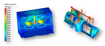
Multiphysics coupling: Moldex3D runs the full injection-molding sequence (filling → packing/holding → cooling → ejection → post-molding) and carries temperatures, pressures, residual stresses, and degree of crystallinity forward into the warpage step. Warpage is a result of those interacting effects, so coupling is essential.
Realistic material behavior: It supports temperature- and pressure-dependent viscosity, viscoelasticity, crystallization kinetics for semi-crystalline polymers, and thermoelastic properties. Accurate material behavior drives realistic shrinkage and stress prediction.
PVT / compressibility modeling: Pressure–volume–temperature data (PVT or Tait models) determine volumetric shrinkage under pressure and temperature. This is one of the single most important inputs for correct warpage magnitude.
Fiber orientation and anisotropy: For fiber-filled polymers, Moldex3D predicts fiber orientation during flow and applies anisotropic mechanical properties in the warpage calculation — crucial for reproducing direction-dependent distortion.
Residual stress and sink/surface effects: The tool predicts residual stress fields and local sink marks from non-uniform cooling and packing, both of which influence final deformation.
High-fidelity meshing & solver: The solver maps process results onto a structural mesh and uses robust solvers for nonlinear thermomechanical response, giving accurate displacement predictions even for complex thin-walled parts.
Tool & boundary condition realism: It models mold cooling channels, mold temperature distribution, part–mold contact, clamping/ejection conditions and support points — all of which affect distortion in the real part.
Validation and calibration features: Built-in workflows let you compare simulation vs. measurement and update inputs to improve correlation (e.g., adjust PVT parameters, thermal contact resistances, or material data).
How to get warpage predictions as close to reality as possible (practical checklist)
Use accurate material data
Provide PVT data or validated Tait parameters.
Supply temperature-dependent elastic modulus and CTE, and viscoelastic/relaxation data when available.
For filled grades, provide fiber content and, if possible, measured anisotropic properties.
Replicate the actual process
Use measured melt and mold temperatures, injection speed/pressure curves, packing/hold profile and cycle times from your molding machine.
Include real gate, runner and cooling channel geometry.
Mesh smartly
Refine mesh in thin walls, ribs, and critical features.
Ensure the process mesh maps well to the warpage structural mesh — avoid overly coarse mapping.
Model the tooling and boundary conditions
Include mold temperature gradients, insert components, and realistic support/ejection constraints.
Consider tool deformation if your mold steel is thin or fixtures are flexible.
Account for crystallization & orientation (if relevant)
Turn on crystallization kinetics for semi-crystalline polymers and fiber orientation prediction for reinforced materials.
Validate & calibrate
Measure part shrinkage/warpage on first-off parts.
Do short-shot and PVT bench tests if possible, and use them to tune your material model.
Run sensitivity analysis to find which inputs most affect warpage for your part.
Document variability
Run multiple simulations across realistic ranges (mold temp ±, melt temp ±, packing pressure ±) to understand expected variability.
Common limitations and where discrepancies come from
Material variability and incomplete material data (polymer lots, fillers, moisture content).
Inaccurate or incomplete PVT or viscoelastic data.
Unknown or changing process conditions on the shop floor (mold temperature non-uniformity, machine control variations).
Tool tolerances, warpage induced by clamping stress or handling, and ejection distortions that aren’t fully modeled.
Measurement errors in the “real” part used for validation.
What simulation teams typically do to close the gap
Perform targeted material characterization (PVT, DMA, rheology).
Instrument mold/cavity temps and cycle profiles for input.
Use optical scanning of first-off parts for quantitative validation.
Iterate the model (calibrate PVT, thermal contact, etc.) and re-run sensitivity tests until correlation is within acceptable tolerance.
Quick rule of thumb
If you want per cent-level accuracy in warpage magnitude, invest in good PVT and temperature-dependent mechanical data plus measured process conditions. Without those, even the best solver will be limited.
In short, Moldex3D transforms warpage prediction from guesswork into a science-driven engineering tool.