
Automating Electrode Design and Manufacturing with VISI
Complex injection moulds and dies frequently contain deep ribs, narrow slots, sharp internal corners, intricate cavities and other features that are difficult or impossible to manufacture efficiently using conventional cutting tools alone.
Electrical Discharge Machining (EDM) provides an effective solution for producing these features, but every EDM operation begins with an accurately designed electrode.
As mould complexity increases, manually designing dozens or even hundreds of electrodes can become a significant engineering bottleneck. Electrode geometry has to correspond correctly with the burn area, clear surrounding geometry, connect to the appropriate holder and ultimately be manufactured accurately from copper, graphite or another suitable electrode material.
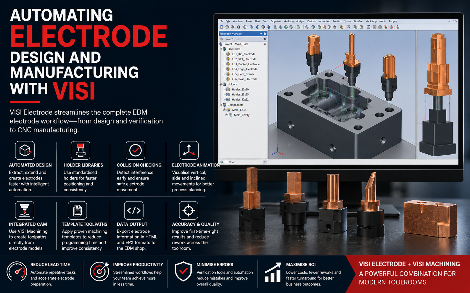
VISI Electrode, part of Hexagon's VISI CAD/CAM environment for mould and die manufacturing, addresses this challenge through dedicated tools for electrode creation, management, verification and manufacturing preparation.
Why Electrode Design Can Become a Manufacturing Bottleneck
Traditional electrode design involves much more than simply copying a cavity surface. Engineers typically have to identify the exact burn region, extract the required faces, extend surrounding surfaces, define clearances, create electrode stock, orient the electrode, position the holder and prepare information for both CNC machining and the EDM department.
When these operations are performed through disconnected CAD, CAM and documentation systems, several challenges can arise:
- Excessive manual modelling operations
- Time-consuming surface extraction and extension
- Difficulty handling very small or complex cavity details
- Incorrect electrode orientation
- Electrode-to-component or holder collisions
- Inconsistent electrode naming and identification
- Errors transferring information from design to CNC programming
- Repetitive creation of similar holders and setups
- Difficulty managing engineering changes
- Additional communication between CAD, CAM and EDM departments
Dedicated electrode automation helps replace many of these repetitive activities with a controlled workflow.
What Is VISI Electrode?
VISI Electrode is a specialised module designed for the creation and management of EDM electrodes and their holders. It is particularly relevant to mould and press-tool manufacturers producing detailed or difficult-to-machine features.
Rather than treating electrode creation as an independent CAD operation, VISI integrates electrode design with the surrounding mould-and-die manufacturing environment.
The software combines automation with manual modelling capability. This is important because electrode manufacturing often contains unusual geometry that cannot always be handled through a completely automatic process.
How VISI Automates the Electrode Design Process
1. Identify the EDM Burn Area
The process starts by identifying the section of the mould cavity, core or tooling component that requires EDM machining.
Engineers can define the required region using 2D or 3D boundaries and graphical face selection. This is particularly useful when dealing with complex cavity geometry where manually recreating the required electrode geometry would consume considerable design time.
2. Dynamic Surface Extraction
VISI provides dynamic surface extraction tools that allow the relevant faces of the model to be extracted for electrode creation.
This can significantly simplify the process of building electrodes for ribs, pockets, logos, textured regions, deep cavities and other localised details.
Instead of redrawing the burn geometry from a separate 2D sketch, the designer can work directly from the existing 3D mould geometry.
3. Automatic Surface Extension
Extracting the cavity surface alone is normally not sufficient for producing a practical EDM electrode. Additional geometry may be required around the burn area to create suitable manufacturing and clearance conditions.
VISI supports both linear and tangential surface extension, helping engineers extend electrode surfaces according to surrounding geometry.
Automating these operations can eliminate many repetitive surface-modelling steps associated with conventional electrode design.
4. Build the Electrode Body and Stock
Once the burn geometry has been established, the electrode body can be developed around it. Stock geometry can then be created according to the intended manufacturing method and available electrode material.
Standardising stock dimensions is particularly valuable in toolrooms manufacturing a large number of electrodes because it can simplify material preparation, CNC setup and inventory.
5. Electrode Holder Management
Creating an accurate electrode is only one part of the EDM process. Its relationship with the holder and EDM setup is equally important.
VISI Electrode includes electrode-holder libraries that help engineers select and position holders within the design environment.
Using standardised holders helps improve consistency between the CAD model, CNC machining department and EDM machine setup.
6. Define Electrode Orientation
Not every electrode approaches the component vertically. Complex moulds may require side, angled or inclined EDM operations.
VISI supports visualisation and animation of electrodes in different orientations, including:
- Vertical electrodes
- Side electrodes
- Inclined electrodes
Visualising the electrode movement before manufacturing helps engineers understand whether the proposed EDM approach is practical.
7. Electrode Collision Checking
Collision verification is one of the most important stages in an automated electrode workflow. Even if the burn geometry itself is correct, surrounding portions of the electrode or holder may interfere with the mould component.
VISI Electrode provides collision-checking capabilities to help identify potential interference before the electrode reaches the shop floor.
Detecting these problems digitally can reduce the risk of incorrect electrodes, EDM setup difficulties and unnecessary toolroom rework.
Connecting Electrode Design with CNC Manufacturing
One of the strongest advantages of an integrated CAD/CAM environment is the ability to move electrode information downstream without reconstructing the component in another software system.
Electrodes prepared in VISI Electrode can be used together with VISI Machining to generate CNC toolpaths.
Depending on electrode size and complexity, manufacturing may involve machining strategies such as:
- Face milling
- Rough machining
- Rest roughing
- Semi-finishing
- 3D finishing
- Corner finishing
- Pencil machining
- High-speed machining strategies
- Detail machining using small cutting tools
Template-based machining is particularly valuable when a toolroom repeatedly manufactures electrodes with similar materials, stock dimensions and machining requirements.
Typical Automated VISI Electrode Workflow
3D Mould / Die Model ↓
Identify EDM Burn Area ↓
Extract Required Surfaces ↓
Extend / Repair Electrode Geometry ↓
Create Electrode Body and Stock ↓
Assign Electrode Holder ↓
Define Electrode Orientation ↓
Perform Collision Checking ↓
Generate Electrode Manufacturing Information ↓
Create CNC Toolpaths in VISI Machining ↓
Machine Copper / Graphite Electrode ↓
EDM Setup and Manufacturing
Benefits of Automating Electrode Manufacturing
| Traditional Challenge | VISI-Based Approach | Potential Manufacturing Benefit |
|---|---|---|
| Manual reconstruction of burn geometry | Direct extraction from 3D tooling geometry | Reduced CAD preparation |
| Manual surface extension | Linear and tangential surface extension tools | Faster electrode modelling |
| Repeated holder modelling | Electrode holder libraries | Better standardisation |
| Difficulty verifying electrode access | Electrode animation and positioning | Better process planning |
| Undetected interference | Electrode collision checking | Reduced risk of rework |
| Separate CAD and CAM preparation | Integration with VISI Machining | More connected manufacturing workflow |
| Repeated programming of similar electrodes | Template-based toolpaths | Improved CNC programming productivity |
Managing Multiple Electrodes in Complex Mould Projects
Large moulds can require many different electrodes. Some may perform rough EDM operations, while others are used to produce fine details or achieve specific surface conditions.
As electrode quantity increases, data management becomes almost as important as geometry creation.
A structured electrode management process can help engineers maintain information related to:
- Electrode identification
- Electrode geometry
- Position and orientation
- Holder configuration
- Manufacturing stock
- Machining requirements
- EDM setup information
- Project relationship
Better digital management reduces dependence on manually maintained notes and disconnected files.
Handling Engineering Changes
Engineering modifications are common during mould development. A customer may request a product change after tooling work has already started, or mould trials may identify areas requiring modification.
In a disconnected workflow, engineers may need to manually determine which electrodes are affected and rebuild associated geometry.
Maintaining electrode design closer to the original 3D mould model makes change management more controlled. Engineers can evaluate the modified region and update the required manufacturing information without recreating the entire electrode process from the beginning.
Copper and Graphite Electrode Manufacturing
EDM electrodes are commonly manufactured from materials such as copper and graphite, with material selection depending on application requirements, EDM strategy, surface finish, wear characteristics and shop practices.
Regardless of the electrode material, accurate CNC machining is essential. Small ribs, sharp details and deep features may require sophisticated machining strategies and carefully selected tools.
Integrating electrode design with CAM allows the manufacturing team to work directly from the approved electrode model and reduces unnecessary geometry translation.
Template-Based Electrode Machining
Electrode manufacturing is highly suitable for process standardisation. A toolroom may frequently manufacture electrodes from the same materials using similar cutters, spindle parameters and machining sequences.
VISI Machining can support template-based toolpath strategies, allowing proven machining processes to be reused on new electrode geometries.
This approach can help companies reduce dependence on repetitive CAM programming while maintaining consistent machining practices.
Where VISI Electrode Can Be Used
VISI Electrode is particularly relevant to companies involved in:
- Plastic injection mould manufacturing
- Automotive mould and die production
- Consumer-product tooling
- Medical component mould manufacturing
- Electronics and connector moulds
- Packaging moulds
- Precision tooling
- Press tools and dies
- Toolroom operations
- EDM job shops
VISI as an Integrated Mould and Die Manufacturing Environment
The value of VISI extends beyond electrode design. VISI is developed specifically around mould-and-die engineering and combines capabilities for modelling, mould design, analysis, electrode creation and CNC machining.
This creates the opportunity to maintain more of the tooling process inside a common engineering environment.
A typical integrated workflow can involve:
- Import or create the component CAD model
- Analyse and repair geometry
- Develop mould core and cavity geometry
- Complete mould-tool design
- Identify difficult-to-machine cavity regions
- Create EDM electrodes
- Verify electrode access and collisions
- Generate CNC programs for electrodes
- Machine mould inserts and tooling components
- Complete EDM operations
Connecting these stages can reduce unnecessary file conversion and help maintain consistent design information throughout the tool-manufacturing process.
Automation Does Not Remove Engineering Knowledge
Electrode automation should not be viewed as a replacement for experienced mould designers, CNC programmers or EDM specialists.
Instead, automation removes repetitive geometry preparation and data-management activities, allowing experienced engineers to focus on more important manufacturing decisions.
Decisions involving electrode splitting, burn direction, spark gaps, surface-finish requirements, EDM strategy, material selection, number of electrodes and manufacturing sequence continue to require engineering knowledge.
Why Integrated Electrode Automation Matters for Modern Toolrooms
Mould manufacturers increasingly face shorter delivery schedules, complex component geometry and pressure to reduce tool-manufacturing costs.
Electrode design is an ideal area for automation because it contains many repetitive operations while remaining closely connected to both CAD design and CNC manufacturing.
By integrating electrode design, holder management, verification and machining, VISI can help toolrooms establish a more systematic manufacturing process.
The potential result is not simply faster electrode modelling. The larger objective is to achieve better information continuity from the mould designer to the CNC programmer and ultimately to the EDM machine.
Frequently Asked Questions
What is VISI Electrode?
VISI Electrode is a dedicated module within the VISI environment for creating and managing EDM electrodes and their holders for mould, die and press-tool manufacturing.
Can VISI automatically create electrodes?
VISI provides knowledge-based electrode creation tools that assist with extracting burn surfaces, extending geometry, creating electrodes, assigning holders and managing electrode information. Manual modelling tools remain available for special situations.
Does VISI provide electrode collision checking?
Yes. Electrode collision checking and electrode movement visualisation can help engineers verify the proposed EDM setup before manufacturing.
Can VISI manufacture the electrodes after design?
Electrode geometry created using VISI Electrode can be used with VISI Machining to generate CNC toolpaths, supporting a connected CAD-to-CAM manufacturing workflow.
Can VISI create electrodes for complex mould geometry?
Yes. Dynamic surface extraction, graphical face selection and surface-extension tools are designed to assist with complex and difficult-to-machine regions found in mould and die components.
Who benefits most from VISI Electrode?
Injection mould manufacturers, die manufacturers, precision toolrooms, EDM departments, CNC programming teams and companies producing large numbers of copper or graphite electrodes can benefit from a specialised electrode workflow.
Conclusion
EDM remains an essential manufacturing process for producing complex and difficult-to-machine features in injection moulds, press tools and precision dies. However, conventional electrode preparation can introduce significant CAD modelling, documentation and CNC programming work.
VISI Electrode helps digitalise and automate this process through burn-area extraction, surface extension, electrode and holder creation, collision checking, positioning and manufacturing preparation.
When combined with VISI Machining, the workflow can continue from electrode design into CNC programming, helping create a connected CAD/CAM environment for electrode manufacturing.
For mould and die manufacturers looking to reduce repetitive electrode-design operations, standardise toolroom processes and improve the flow of manufacturing information, integrated electrode automation can become an important part of the digital manufacturing strategy.
Looking to Automate Your Mould & Electrode Manufacturing Process?
Rheologist Gaze & Solutions provides engineering software solutions for mould, die, CAD/CAM and advanced manufacturing applications.
Talk to our team to explore how Hexagon VISI can support mould design, electrode creation and CNC manufacturing workflows within your organisation.
Contact Us