
How NX Mold Wizard Accelerates Injection Mold Design
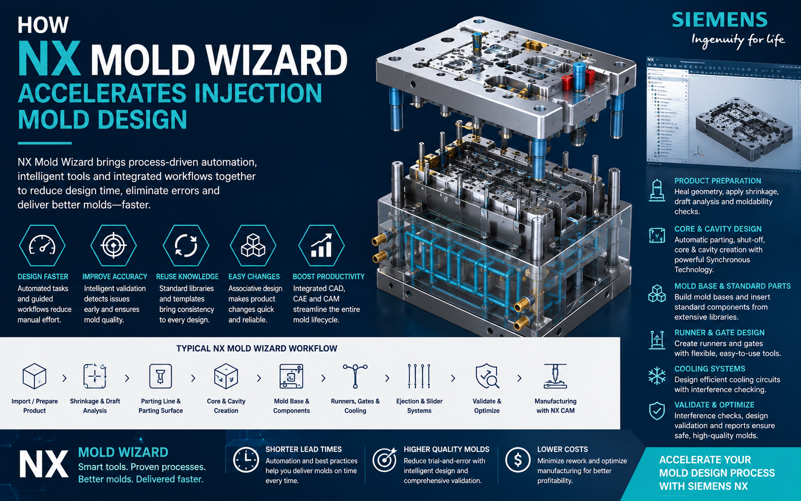
Injection mold design involves much more than creating a core and cavity. Mold designers must evaluate the plastic component, determine parting geometry, build the mold base, position standard components, develop runners and gates, create cooling circuits, prepare ejector systems and validate the complete tool. Siemens NX Mold Wizard brings these activities together in an automated, knowledge-driven mold design environment.
Injection mold manufacturers are under continuous pressure to reduce tool delivery times while managing increasingly complex plastic components.
Traditionally, many mold design activities are performed manually using general-purpose CAD tools. Designers create parting surfaces, model mold plates, position guide pillars, develop cooling channels and manage hundreds of components individually.
These repetitive operations can consume valuable engineering time and introduce opportunities for errors.
Siemens NX Mold Wizard addresses this challenge by combining NX modelling technology with dedicated automation specifically developed for plastic injection mold design.
What Is NX Mold Wizard?
NX Mold Wizard is a specialized mold design environment within Siemens NX that provides a structured workflow for developing plastic injection molds.
Rather than asking designers to construct every element manually, mold-specific tools help automate repetitive operations and guide engineers through the tooling development process.
A typical mold development process can include:
- Product model preparation
- Moldability analysis
- Shrinkage application
- Mold coordinate definition
- Parting-line development
- Core and cavity creation
- Mold-base configuration
- Standard component placement
- Runner and gate design
- Cooling-system design
- Ejector-system development
- Tooling validation
- Drawing preparation
- CNC manufacturing
1. Faster Product Model Preparation
Mold development begins with the plastic component supplied by the customer or product design team.
This geometry may originate from NX or another CAD platform. Before tooling development begins, designers need to evaluate the model and prepare it for the molding process.
Typical preparation activities can include:
- Checking product geometry
- Establishing tooling direction
- Applying material shrinkage
- Defining mold coordinates
- Identifying undercuts
- Evaluating draft requirements
- Preparing multiple cavity layouts
Having these operations available within the mold-design environment reduces unnecessary file transfers and helps establish an accurate starting point for downstream tool design.
2. Automated Core and Cavity Development
Creating core and cavity geometry is one of the most critical stages of injection mold design.
With a conventional modelling approach, engineers may manually identify parting boundaries, create shut-off surfaces, build parting surfaces and perform Boolean operations to separate the mold.
NX Mold Wizard provides dedicated functionality to support this process.
Typical Core and Cavity Workflow
- Define the mold opening direction.
- Analyse the product geometry.
- Identify parting edges.
- Create or modify shut-off regions.
- Develop parting surfaces.
- Create the mold workpiece.
- Separate the workpiece into core and cavity components.
Automating and structuring these operations can significantly reduce repetitive CAD modelling, particularly for complex molded parts.
3. Associative Mold Design
Product changes are common during tool development. Customers may modify wall thickness, ribs, bosses, openings, logos or other component features after the mold design has already started.
If the mold model is disconnected from the original product geometry, every engineering change can result in extensive manual rework.
NX supports associative relationships between product and tooling geometry, helping designers update affected mold components when product geometry changes.
4. Mold Base Automation
Building a mold base manually can require significant CAD work. Designers must create and position multiple plates, guide systems, fasteners, support components and other mold elements.
NX Mold Wizard provides mold-base tools and reusable libraries that help engineers configure the mold structure much more efficiently.
Depending on the tooling requirements, the mold base can contain components such as:
- Top clamping plate
- Cavity plate
- Core plate
- Support plate
- Spacer blocks
- Ejector plates
- Bottom clamping plate
- Guide pillars
- Guide bushes
- Support pillars
Standardized mold-base configurations help reduce repetitive design work while supporting company-specific tooling standards.
5. Standard Mold Component Libraries
A typical injection mold contains many purchased and standardized components. Recreating these items for every new project is unnecessary and inefficient.
Mold Wizard allows designers to work with standard component libraries so common mold elements can be selected and positioned within the assembly.
These may include:
- Ejector pins
- Sprue bushes
- Locating rings
- Guide components
- Screws
- Support pillars
- Return pins
- Cooling fittings
- Slides and related tooling elements
Reusing standard components improves consistency while reducing manual modelling and component-selection time.
6. Runner and Gate Design
The runner and gate system controls how molten polymer travels from the injection molding machine nozzle into the mold cavity.
Poor runner or gate design can contribute to filling problems, weld lines, pressure loss, excessive material consumption and other molding issues.
NX Mold Wizard provides tools that allow designers to develop the feed system directly within the mold assembly.
Typical elements include:
- Sprue
- Main runner
- Branch runners
- Cold slug wells
- Gate geometry
Maintaining runner geometry within the same digital model provides better coordination with the surrounding mold components.
7. Cooling-System Design
Cooling can have a major influence on injection molding cycle time, part quality and dimensional stability.
Mold designers therefore need to create cooling channels that provide adequate heat removal while avoiding interference with ejector pins, screws, cavities, inserts and other components.
NX Mold Wizard supports cooling-system development within the mold model, allowing designers to create and manage cooling passages while considering nearby tooling geometry.
Cooling layouts may include:
- Straight drilled channels
- Cross-drilled cooling circuits
- Baffles
- Bubblers
- Cooling connectors
- Plugged drilling passages
8. Ejection-System Development
Once the molded component has cooled sufficiently, it needs to be removed from the core without damaging the product.
Ejection-system development therefore requires careful consideration of:
- Ejector-pin locations
- Pin diameters
- Ejector travel
- Product appearance requirements
- Rib and boss locations
- Cooling-channel interference
- Mold-component interference
Using dedicated mold design tools helps engineers position and manage these components more systematically than modelling each part individually.
9. Slider, Lifter and Undercut Solutions
Plastic components frequently contain undercuts that cannot be released using only the primary mold opening direction.
These situations may require mechanisms such as:
- Side cores
- Slides
- Angle pins
- Lifters
- Mechanical inserts
Modelling these mechanisms inside the complete tooling assembly allows engineers to understand movement, accessibility and surrounding clearances before manufacturing begins.
10. Mold Design Validation
Injection molds contain many closely positioned components. A small design interference can cause significant problems during assembly or mold operation.
Digital validation allows designers to identify potential problems earlier in the development cycle.
Validation may include checking:
- Component interference
- Ejector clearance
- Cooling-channel interference
- Slider movement
- Fastener locations
- Mold opening sequences
- Assembly relationships
Typical NX Mold Wizard Workflow
Customer / Product CAD Model ↓
Product Analysis & Preparation ↓
Define Mold Direction & Shrinkage ↓
Parting Line & Parting Surface ↓
Create Core & Cavity ↓
Configure Mold Base ↓
Add Standard Mold Components ↓
Create Runner & Gate System ↓
Design Cooling Circuits ↓
Create Ejection System ↓
Add Slides / Lifters Where Required ↓
Validate Complete Mold Assembly ↓
Create Drawings & BOM ↓
NX CAM Manufacturing
NX Mold Wizard vs Conventional Mold Design
| Design Activity | Conventional CAD Workflow | NX Mold Wizard Workflow |
|---|---|---|
| Product Preparation | Multiple manual modelling operations | Structured mold-specific preparation workflow |
| Core & Cavity | Manual surface and Boolean construction | Dedicated core/cavity development tools |
| Mold Base | Build or import components individually | Reusable mold-base configurations |
| Standard Components | Manual component modelling and positioning | Standardized libraries and placement tools |
| Cooling | Manual hole and channel creation | Dedicated cooling-system workflow |
| Engineering Changes | Manual downstream corrections | Associative product-to-tool relationships |
| Validation | Visual/manual checking | Integrated digital validation |
| Manufacturing | Export data to separate CAM environment | Connected NX CAD/CAM workflow |
How NX Mold Wizard Accelerates Design
1 Automates Repetitive Tasks
Mold-specific functions reduce the need to repeatedly create standard tooling geometry from scratch.
2 Reuses Engineering Knowledge
Libraries, templates and company standards help experienced toolmaking knowledge become part of the digital process.
3 Improves Design Consistency
Standardized workflows can help different designers follow consistent tooling practices.
4 Handles Changes Better
Associative relationships help reduce the amount of manual rework required after product design modifications.
5 Reduces Design Errors
Digital validation helps identify clearance and interference issues before tooling components are manufactured.
6 Connects Design to CAM
Mold components can continue into NX manufacturing workflows without unnecessary geometry recreation.
From Mold Design to CNC Manufacturing
One of the major advantages of using NX for tooling is that mold design does not have to remain an isolated CAD activity.
Once the mold is approved, core inserts, cavity inserts, sliders, electrodes, mold plates and other components can move into NX CAM for CNC programming.
Typical mold-manufacturing operations can include:
- High-speed roughing
- Rest roughing
- Semi-finishing
- 3D surface finishing
- Corner machining
- Hole making
- Deep-hole drilling
- Multi-axis machining
- Electrode machining
Keeping design and manufacturing within a common digital environment can reduce data translation and improve communication between the mold-design and CNC-programming teams.
Better Response to Engineering Changes
Product changes are almost unavoidable in tooling projects. What matters is how quickly the mold manufacturer can respond.
Because NX Mold Wizard is built around associative modelling, modifications to the product model can be evaluated against the associated tooling components.
This can help reduce the risk of manufacturing components based on outdated product geometry.
Suitable Applications for NX Mold Wizard
NX Mold Wizard can support injection mold development across a wide variety of industries.
- Automotive plastic components
- Consumer products
- Medical plastic components
- Electrical housings
- Electronic connectors
- Home appliances
- Industrial plastic components
- Packaging products
- Precision engineering components
- Multi-cavity production molds
Who Should Consider NX Mold Wizard?
The solution is particularly relevant to:
- Injection mold manufacturers
- Mold design companies
- Toolrooms
- Plastic product manufacturers with in-house tooling
- Automotive tooling suppliers
- Engineering design consultancies
- Companies using NX for CAD and CAM
- Manufacturers looking to standardize mold-design processes
Automation Does Not Replace the Mold Designer
Injection mold design is highly dependent on engineering experience. Software automation can reduce repetitive CAD work, but it cannot replace important tooling decisions.
Experienced mold designers still need to determine:
- Optimal parting strategy
- Core and cavity construction
- Gate location
- Runner design
- Cooling philosophy
- Ejection strategy
- Slide and lifter mechanisms
- Mold materials
- Tool maintenance requirements
- Manufacturing feasibility
Why NX Mold Wizard Matters for Modern Toolrooms
Today's mold manufacturers compete on more than machining capability. They also compete on engineering speed, change-management capability, first-time-right tooling and overall project lead time.
A digital mold-development platform helps bring product data, mold design, validation and manufacturing into a more connected workflow.
Instead of treating CAD, mold design and CNC programming as independent departments, NX allows companies to develop a more integrated design-to-manufacturing process.
Frequently Asked Questions
What is Siemens NX Mold Wizard?
NX Mold Wizard is a specialized tooling environment within Siemens NX that helps automate injection mold development, including product preparation, core and cavity design, mold bases, standard components, runners, cooling and tooling validation.
Can NX Mold Wizard create core and cavity geometry?
Yes. Dedicated tools help designers define parting geometry and create core and cavity components from the plastic product model.
Does NX Mold Wizard support mold-base design?
Yes. Mold Wizard includes workflows for configuring mold bases and positioning standard tooling components within the mold assembly.
Can NX Mold Wizard design runners and cooling channels?
Yes. Runner, gate and cooling-system design can be developed within the overall mold design workflow.
Does NX Mold Wizard help when the product design changes?
Associative relationships between product and tooling geometry help designers manage downstream mold modifications more efficiently when the original component changes.
Can NX Mold Wizard work with NX CAM?
Yes. Tooling components created in NX can continue into NX CAM for CNC programming, creating a connected design and manufacturing workflow.
Conclusion
Injection mold design contains many repetitive yet highly interconnected engineering activities. Performing all of these manually can increase design time and make engineering changes difficult to control.
NX Mold Wizard accelerates injection mold design by combining automation, reusable tooling knowledge, associative modelling and mold-specific workflows.
From product preparation and core/cavity development to mold-base creation, cooling, ejection, validation and CNC manufacturing, NX provides a connected environment for developing injection molds more efficiently.
For mold manufacturers seeking shorter engineering lead times, greater standardization and closer integration between design and manufacturing, NX Mold Wizard can become a central element of a modern digital toolroom.
Looking to Accelerate Your Injection Mold Design Process?
Rheologist Gaze & Solutions provides Siemens engineering software solutions for product development, mold design, simulation and manufacturing applications.
Talk to our team to explore how Siemens NX Mold Wizard can help automate your mold design workflow from product geometry through core/cavity development and CNC manufacturing.
Talk to Our NX Team