
VISI Progress for Progressive-Die Design: From Strip Layout to Manufacturing
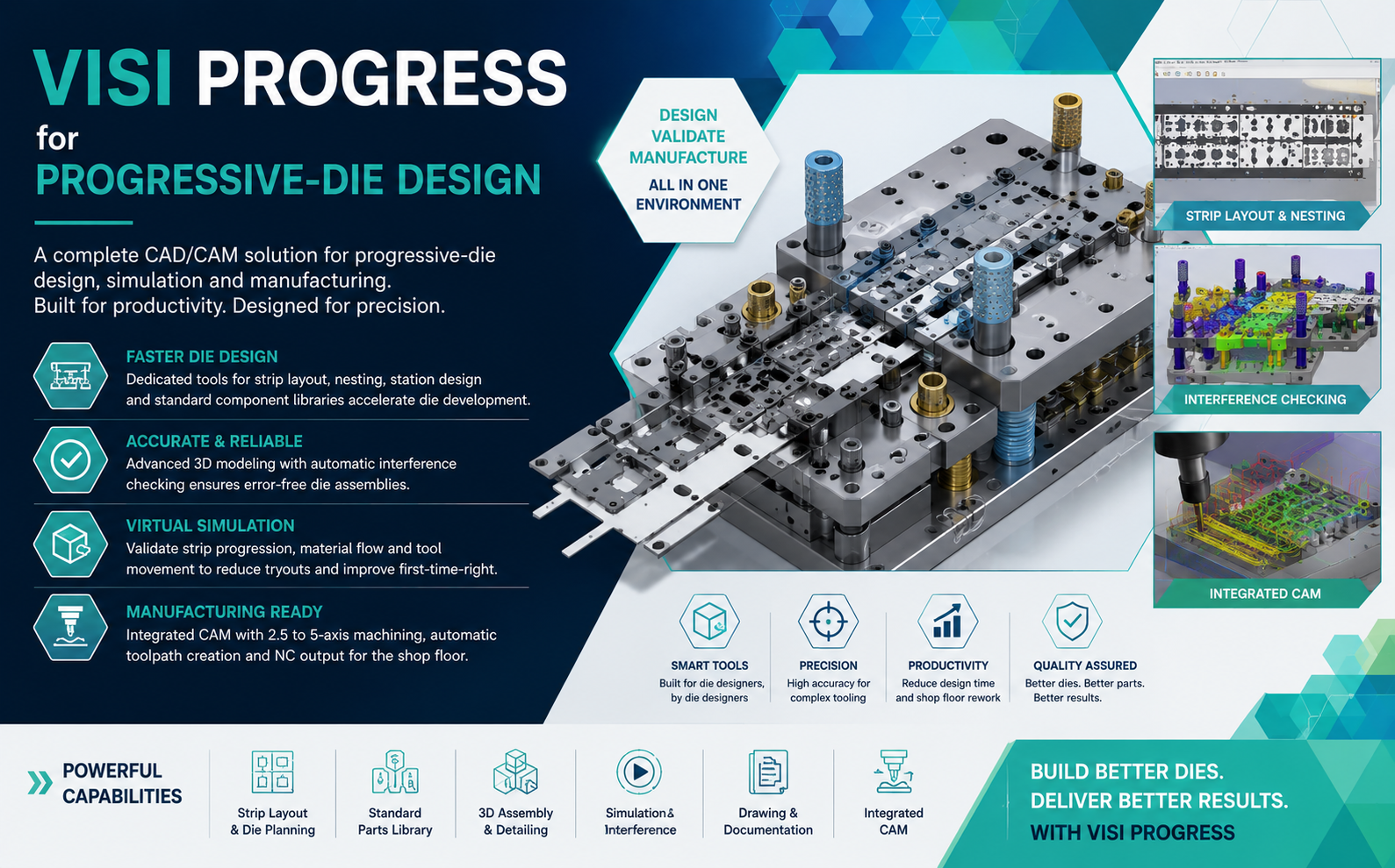
Progressive die development requires a high level of accuracy in strip planning, station definition, component placement, interference checking and manufacturing preparation. VISI Progress helps bring these activities into a dedicated CAD/CAM environment designed specifically for progressive die and press-tool manufacturers.
Progressive dies are widely used for the high-volume production of sheet metal components in industries such as automotive, electrical, electronics, appliances, industrial equipment and consumer products.
Although progressive tooling can deliver very high productivity on the press, designing the tool itself is a complex engineering task. The designer must determine how the sheet progresses through multiple stations while maintaining material stability, dimensional accuracy, forming feasibility and reliable tool operation.
VISI Progress is developed to support this specialised workflow by combining strip development, die design, standard component management, verification, documentation and CAM preparation in a connected environment.
What Is Progressive Die Design?
A progressive die performs several sheet metal operations as a continuous strip moves through a sequence of stations. Each press stroke completes one or more operations, gradually transforming the raw strip into the final component.
Typical progressive die operations can include:
- Blanking
- Piercing
- Notching
- Lancing
- Bending
- Flanging
- Embossing
- Coining
- Forming
- Cut-off and part separation
The quality of the final tool depends heavily on how well the strip layout and individual stations are planned during the design phase.
Why Progressive Die Design Is Challenging
Progressive tooling combines product engineering, sheet metal forming knowledge, mechanical design and manufacturing planning.
Designers have to consider several variables simultaneously:
- Strip width and material utilisation
- Number of stations
- Pitch between stations
- Carrier design
- Part orientation
- Forming sequence
- Springback considerations
- Tool clearances
- Punch and die arrangement
- Strip lifting and guiding
- Press direction and accessibility
- Interference between moving components
- Maintenance requirements
When these activities are performed using generic CAD software, designers may spend substantial time creating repeated geometry, positioning standard components and manually checking tooling relationships.
How VISI Progress Supports Progressive Die Development
1. Part Analysis and Design Preparation
The process begins with the sheet metal component model. Designers can evaluate the component geometry and determine the manufacturing sequence required to produce the part through a progressive tool.
Product geometry can be used directly as the basis for developing forming stages and intermediate strip conditions.
2. Strip Layout Development
Strip layout is one of the most important activities in progressive die design because it defines how the component will move through the tool.
VISI Progress helps designers create and optimise strip layouts while considering:
- Part orientation
- Strip pitch
- Material width
- Carrier position
- Station sequence
- Material utilisation
- Blank progression
An effective strip layout can reduce material waste while also providing adequate strip strength and stability during press operation.
3. Progressive Station Planning
Once the strip layout has been defined, individual operations can be assigned to each station.
The designer can distribute forming, piercing, trimming and other operations across the required sequence to maintain a stable process.
Proper station planning helps prevent excessive load concentration and reduces the possibility of strip distortion during production.
4. Punch and Die Design
Progressive tools contain many punches, dies, inserts, pilots and supporting components. VISI Progress provides dedicated tooling capabilities that help designers develop these elements within the main die assembly.
By working directly from the strip and component geometry, the designer can maintain better consistency between the stamping operations and the physical tooling.
5. Standard Component Libraries
Progressive dies include many standard components that are repeatedly used across different projects.
Typical examples include:
- Guide pillars
- Guide bushes
- Springs
- Fasteners
- Dowel pins
- Strippers
- Lifters
- Pilots
- Retainers
- Wear plates
Using predefined component libraries allows designers to reuse standard parts instead of rebuilding them from scratch for every project.
6. Die Assembly Development
Progressive dies may contain hundreds of individual components. Managing the relationship between these parts is therefore a major part of the design process.
VISI provides 3D assembly functionality that helps engineers build the complete tool while maintaining control over component positions and relationships.
7. Interference and Collision Checking
A progressive die contains both fixed and moving components. Even a small interference problem can result in assembly difficulties, tool damage or unexpected press downtime.
Digital interference checking helps identify collisions between tool components before manufacturing begins.
This is particularly valuable for:
- Punch-to-die relationships
- Stripper movement
- Cam movements
- Lifters
- Pilots
- Forming inserts
- Standard component positioning
Virtual Validation Before Tool Manufacturing
Progressive dies are expensive manufacturing assets. Discovering a design issue after machining and assembly can result in considerable rework and schedule delays.
Virtual design validation gives engineers an opportunity to review strip progression, component relationships and tool movements before committing the design to manufacturing.
This digital validation process can help reduce trial-and-error during the physical tool-building stage.
Typical VISI Progress Workflow
Import / Create Sheet Metal Part ↓
Analyse Component Geometry ↓
Create Blank and Forming Stages ↓
Develop Strip Layout ↓
Define Progressive Stations ↓
Create Punches and Die Inserts ↓
Add Standard Components ↓
Build Complete Die Assembly ↓
Perform Interference Checking ↓
Create Drawings and Documentation ↓
Generate CNC Toolpaths ↓
Manufacture and Assemble Progressive Die
Integrated CAD and CAM for Die Manufacturing
Progressive die design does not end when the 3D assembly is complete. Every punch, insert, plate and forming element has to be manufactured accurately.
The VISI environment connects tooling design with CAM preparation, helping manufacturing teams move from approved geometry into CNC programming without rebuilding models in an independent CAM system.
Depending on tooling geometry, manufacturing may involve:
- 2D machining
- 2.5-axis machining
- 3-axis roughing
- High-speed finishing
- Rest machining
- Hole machining
- Multi-axis machining
- Electrode manufacturing
Maintaining CAD and CAM data within a connected environment can help reduce geometry translation and improve data consistency between design and manufacturing teams.
Automating Repetitive Design Tasks
Progressive die design contains many repeated operations. Standard plates, punches, guide components and fasteners often follow established company design practices.
By using libraries, standardised templates and dedicated tooling functions, VISI Progress can help reduce the amount of repetitive CAD modelling required for every new tool.
This enables engineers to spend more time on important process decisions such as:
- Forming sequence optimisation
- Material flow
- Strip stability
- Die strength
- Maintenance accessibility
- Press compatibility
- Cycle reliability
Progressive Die Design: Conventional CAD vs VISI Progress
| Design Activity | Conventional CAD Approach | VISI Progress Approach |
|---|---|---|
| Strip Layout | Manual geometry and station planning | Dedicated progressive strip development tools |
| Component Placement | Repeated modelling and positioning | Reusable standard component libraries |
| Tool Assembly | General-purpose assembly workflow | Tooling-focused 3D design environment |
| Interference Checking | May require manual review | Digital collision and interference verification |
| Engineering Changes | Multiple disconnected updates | More integrated design relationships |
| Manufacturing | Export geometry to separate CAM software | Integrated CAD/CAM environment |
| Documentation | Separate drawing preparation | Drawings developed from the tooling model |
Better Material Utilisation Through Strip Planning
Raw material represents a significant part of the cost of high-volume stamped components. Even a small improvement in material utilisation can become important when millions of parts are produced.
Digital strip development allows designers to evaluate different part orientations and strip configurations before finalising the tooling concept.
The objective is to achieve a balance between:
- Low scrap percentage
- Reliable carrier strength
- Stable strip feeding
- Required forming space
- Tool strength
- Practical die construction
Handling Engineering Changes in Progressive Tooling
Customer design changes can occur even after tool design work has started. When CAD data is highly disconnected, a product modification may require significant manual updating across strip, tooling and manufacturing data.
A more integrated design environment helps engineers identify affected tooling areas and update the related design information in a more structured manner.
Better change management can help reduce duplicated work and minimise the possibility of outdated geometry reaching the shop floor.
Applications of VISI Progress
VISI Progress can be used across many manufacturing sectors where progressive stamping is required.
- Automotive components
- Electrical terminals
- Electronic connectors
- Battery components
- Appliance parts
- Brackets and clips
- Precision sheet metal components
- Consumer product components
- Industrial hardware
- High-volume stamped parts
Who Can Benefit from VISI Progress?
VISI Progress is particularly suitable for:
- Progressive die manufacturers
- Press-tool design companies
- Automotive stamping suppliers
- Sheet metal component manufacturers
- Precision toolrooms
- Tool and die engineering departments
- Companies seeking to standardise die design processes
- Manufacturers looking for integrated CAD/CAM workflows
Key Benefits of VISI Progress
- Faster die development: reduce repetitive modelling and tooling preparation.
- Improved consistency: reuse standard components and proven design practices.
- Better strip planning: digitally evaluate progressive station sequences.
- Reduced design errors: verify component clearances and interference before machining.
- Improved manufacturing communication: maintain consistent 3D tooling data.
- Connected CAD/CAM workflow: move tooling components directly into CNC programming.
- Better change management: reduce duplicated engineering work when designs change.
- Shorter tool development cycles: improve the flow from concept to tool manufacturing.
Why Dedicated Die Design Software Matters
General-purpose CAD software can be used to model almost any mechanical product, including progressive dies. However, toolmakers frequently perform specialised operations that are not common in general mechanical design.
Strip planning, blank progression, punch development, standard die component placement and tool verification are repeated activities in press-tool engineering.
A dedicated environment such as VISI Progress is designed around these workflows, allowing software automation to support the engineering methods already used by experienced die designers.
Automation Supports, Rather Than Replaces, Die Designers
Progressive die design remains a highly specialised engineering discipline.
Software can automate repeated modelling operations and provide digital validation tools, but critical decisions still depend on engineering knowledge.
Experienced designers must still determine:
- The most reliable strip progression
- Appropriate forming sequence
- Carrier configuration
- Critical clearances
- Tool materials
- Maintenance strategy
- Press load distribution
- Die construction methodology
The role of automation is to reduce repetitive work and provide engineers with better digital tools for making these decisions.
Frequently Asked Questions
What is VISI Progress?
VISI Progress is a specialised CAD/CAM solution designed to support progressive die and press-tool development, including strip planning, station design, tooling creation, assembly verification and manufacturing preparation.
Can VISI Progress be used for strip layout design?
Yes. Strip layout development is a core part of the progressive die workflow, helping designers define part orientation, pitch, station sequence, carriers and material progression.
Does VISI Progress help with progressive die automation?
Yes. Dedicated tools, reusable libraries and specialised design functions help reduce repetitive modelling and accelerate progressive tool development.
Can progressive dies designed in VISI be manufactured using CAM?
Yes. The VISI environment includes machining capabilities that allow punches, inserts, plates and other tooling components to move from design into CNC programming.
Which industries use progressive die design software?
Progressive die software is commonly used in automotive, electrical, electronics, appliance, battery, industrial equipment and high-volume sheet metal manufacturing.
Conclusion
Progressive die design combines complex sheet metal process planning with detailed tooling engineering. As tools become more complex and delivery schedules become shorter, relying heavily on repetitive manual CAD operations can increase engineering time and risk.
VISI Progress provides a dedicated environment for progressive die development, supporting strip layout, station planning, tooling design, component management, interference checking, documentation and manufacturing preparation.
By connecting progressive die design with an integrated CAD/CAM workflow, toolmakers can standardise engineering processes, improve design reliability and create a smoother path from the original component geometry to the finished production tool.
Looking to Improve Your Progressive Die Design Process?
Rheologist Gaze & Solutions provides engineering software solutions for mould, die, CAD/CAM and advanced manufacturing applications.
Explore how Hexagon VISI Progress can support your strip development, progressive die design and manufacturing workflow.
Contact Us