
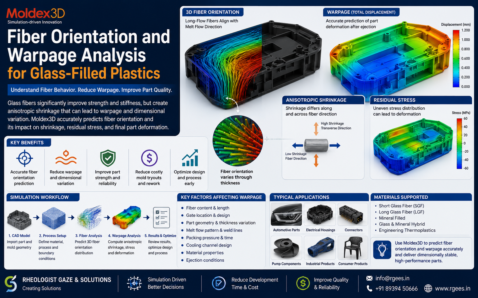
Fiber Orientation and Warpage Analysis for Glass-Filled Plastics
Understand how glass-fiber orientation during injection moulding affects anisotropic shrinkage, residual stress, dimensional stability and final part warpage.
For this reason, accurately predicting fiber orientation and warpage in glass-filled plastics is critical when developing precision injection moulded components.
Why Use Glass-Filled Plastics?
Adding short or long glass fibers to a thermoplastic can significantly change its engineering performance.
Higher Strength
Glass fibers can reinforce the polymer matrix and improve structural performance.
Higher Stiffness
Fiber-reinforced grades can offer greater rigidity than equivalent unfilled polymers.
Improved Dimensional Performance
Appropriate fiber reinforcement can improve dimensional performance, although orientation must be carefully controlled.
The Challenge: Fiber Reinforcement Creates Anisotropy
An unfilled polymer is often approximated as having more uniform properties in different directions.
Fiber-filled materials behave differently.
As the molten polymer flows through the cavity, glass fibers rotate and orient according to the local flow field.
A glass-filled moulded part can therefore shrink, deform and carry load differently along the fiber direction compared with across the fiber direction.
What Is Fiber Orientation in Injection Moulding?
Fiber orientation describes the direction in which reinforcing fibers are aligned inside the moulded component.
During injection moulding, fiber alignment is influenced by factors such as:
- Melt-flow direction
- Gate location
- Flow velocity
- Shear rate
- Part thickness
- Wall transitions
- Weld-line formation
- Material rheology
- Fiber aspect ratio
- Processing conditions
Fiber Orientation Is Not Uniform Through the Part Thickness
Fiber orientation can vary significantly through the thickness of an injection moulded component.
Near the cavity wall, high shear can orient fibers strongly along the flow direction, while the orientation closer to the centre of the flow may be different.
This creates a complex three-dimensional fiber-orientation structure inside the component.
How Fiber Orientation Develops During Injection Moulding
Melt Enters the Cavity
Fiber-filled polymer enters through the gate and begins flowing through the cavity.
Fibers Rotate
Local flow velocity and shear conditions cause the fibers to rotate and align.
Orientation Develops
Different regions of the component develop different fiber directions.
Properties Become Directional
Shrinkage and mechanical behaviour are influenced by the resulting fiber orientation.
How Fiber Orientation Leads to Warpage
The important point is that warpage in fiber-filled plastics is not only a cooling problem.
Fiber orientation changes the shrinkage behaviour of the material, which can create different contraction rates in different directions.
What Is Anisotropic Shrinkage?
Anisotropic shrinkage means that shrinkage is different depending on direction.
In glass-fiber-filled polymers, shrinkage along the fiber direction can differ from shrinkage transverse to the fibers.
If orientation varies across the part, these directional shrinkage differences can create bending, twisting or other dimensional changes.
Main Causes of Warpage in Glass-Filled Plastics
Warpage Is Usually the Result of Several Interacting Effects
Why Gate Location Matters for Glass-Filled Parts
Gate location does more than determine how the cavity fills.
It also defines the main melt-flow directions, which can strongly affect local fiber orientation.
Moving the gate can therefore change:
- Fiber alignment
- Weld-line position
- Shrinkage distribution
- Mechanical properties
- Part warpage
Fiber Orientation Around Weld Lines
When two melt fronts meet, fiber orientation around the weld region can be very different from the surrounding material.
This can affect both:
- Structural performance
- Local deformation behaviour
For structural glass-filled parts, understanding the interaction between weld lines and fiber orientation can therefore be very important.
Does Higher Glass-Fiber Content Always Reduce Warpage?
Not necessarily.
Increasing glass-fiber content can improve stiffness and reduce some types of shrinkage, but it can also increase the importance of directional behaviour.
The final result depends on factors including:
- Fiber percentage
- Fiber length
- Fiber orientation
- Part geometry
- Gate design
- Mould cooling
- Polymer matrix
- Processing conditions
Short Glass Fiber vs Long Glass Fiber
| Factor | Short Glass Fiber | Long Glass Fiber |
|---|---|---|
| Fiber Length | Shorter reinforcement | Longer reinforcement |
| Flow Interaction | Significant | Can be more complex |
| Mechanical Reinforcement | Good | Potentially stronger depending on design and process |
| Orientation Importance | High | Very high |
| Fiber Breakage Concern | Relevant | Often especially important |
| Warpage Prediction | Requires orientation-aware analysis | Requires detailed fiber-aware analysis |
Why Simulation Is Important for Fiber-Reinforced Plastics
The internal fiber pattern cannot normally be understood completely from the finished CAD model alone.
Simulation provides a way to predict how fiber orientation develops during the actual mould-filling process.
Moldex3D's Fiber capability is designed to simulate 3D fiber orientation and use that information to evaluate anisotropic properties, shrinkage and warpage in short- and long-fiber-reinforced plastics.
Fiber Orientation Analysis with Moldex3D
Moldex3D Fiber can be used to visualize fiber orientation and evaluate process-induced anisotropic thermo-mechanical properties for fiber-reinforced materials.
This allows engineers to study:
3D Fiber Orientation
Visualize how fibers align throughout the moulded component.
Anisotropic Shrinkage
Evaluate directional shrinkage influenced by reinforcement orientation.
Mechanical Properties
Assess how fiber orientation changes process-induced material properties.
Warpage
Use fiber orientation and material behaviour to improve deformation prediction.
Fiber Length
For relevant reinforced-material workflows, fiber-length effects can also be important to performance prediction.
Structural Performance
Fiber orientation data can support downstream evaluation of reinforced component performance.
Moldex3D Warpage Analysis for Fiber-Filled Materials
For fiber-filled plastics, accurate warpage analysis requires more than simply applying isotropic material shrinkage.
Moldex3D Warp incorporates fiber-orientation results together with fiber-composite theories to predict anisotropic shrinkage and residual-stress effects in fiber-filled parts.
This helps engineers distinguish between different warpage-driving mechanisms and identify where design or process changes may be most effective.
What Should Engineers Review in a Fiber Analysis?
| Simulation Result | Why It Matters |
|---|---|
| Fiber Orientation | Shows reinforcement direction throughout the component |
| Flow Pattern | Explains why local fiber directions develop |
| Weld Lines | Highlights areas where orientation and strength may change |
| Volumetric Shrinkage | Helps understand local contraction tendency |
| Temperature Distribution | Identifies cooling imbalance |
| Residual Stress | Shows stresses that can contribute to deformation |
| Warpage Displacement | Shows final directional deformation |
| Mechanical Properties | Indicates orientation-dependent stiffness or strength effects |
How to Reduce Warpage in Glass-Filled Injection Molded Parts
Optimize Gate Location
Use gate placement to create more favourable filling and fiber orientation patterns.
Improve Wall Thickness
Avoid unnecessary thickness variation that can amplify differential shrinkage.
Balance Cooling
Reduce temperature differences between different regions and mould surfaces.
Optimize Process Settings
Review filling, packing and cooling conditions that influence shrinkage and stress.
Review Rib & Boss Design
Structural features can alter flow, cooling and shrinkage behaviour.
Compare Material Grades
Evaluate how fiber content, fiber length and polymer grade affect deformation.
Why Warpage Cannot Always Be Solved by Process Adjustment Alone
Some warpage problems are mainly caused by process conditions. Others are driven by part geometry or fiber orientation.
If the dominant warpage mechanism is anisotropic shrinkage caused by fiber orientation, changing packing pressure alone may not solve the problem.
Possible causes may include cooling imbalance, volumetric shrinkage, fiber orientation, geometry or residual stress.
Fiber Orientation Also Affects Structural Performance
Fiber orientation affects more than dimensional stability.
Because the reinforcement creates directional material properties, strength and stiffness can also depend on local fiber alignment.
This means the injection moulding process itself can influence the structural behaviour of the final component.
Where Fiber Orientation Analysis Is Most Valuable
Recommended Simulation Workflow for Glass-Filled Parts
Flow Analysis
Evaluate filling pattern, pressure and weld-line locations.
Fiber Analysis
Predict the three-dimensional orientation of reinforcing fibers.
Cooling & Shrinkage
Evaluate thermal behaviour and directional material shrinkage.
Warpage Analysis
Predict final deformation and investigate the dominant warpage causes.
Fiber and Warpage Analysis Support from Rheologist Gaze & Solutions
Rheologist Gaze & Solutions can support injection moulders, product designers and mould manufacturers in evaluating fiber-reinforced plastic components using Moldex3D simulation.
Our engineering support can include:
- Short glass-fiber simulation
- Long fiber-reinforced plastic analysis
- 3D fiber-orientation prediction
- Gate-location optimization
- Warpage investigation
- Anisotropic shrinkage analysis
- Cooling analysis
- Residual-stress investigation
- Material comparison
- Mould design optimization
- Process optimization
- Moldex3D software demonstrations
- Training and technical support
Frequently Asked Questions
Why do glass-filled plastic parts warp?
Glass-filled parts can warp because fiber orientation creates direction-dependent material properties and shrinkage. Cooling imbalance, packing, residual stress and geometry can also contribute.
Why does fiber orientation affect shrinkage?
Reinforcing fibers constrain the polymer differently along and across their direction, creating anisotropic shrinkage behaviour.
Can gate location change part warpage?
Yes. Gate location changes the melt-flow path and fiber orientation, which can significantly alter directional shrinkage and final deformation.
Can Moldex3D predict fiber orientation?
Yes. Moldex3D Fiber provides three-dimensional fiber-orientation simulation for short- and long-fiber-reinforced plastics and uses this information for anisotropic property and warpage evaluation.
Can simulation show whether cooling or fiber orientation is causing warpage?
Warpage simulation can help engineers evaluate different deformation drivers such as uneven shrinkage, thermal effects, residual stress and fiber-orientation-related anisotropy.
Is fiber analysis useful for structural simulation?
Yes. Fiber orientation affects local mechanical properties, so orientation information can be valuable when evaluating the structural performance of reinforced moulded components.
Conclusion: Fiber Orientation Is a Critical Part of Warpage Prediction
Glass-fiber reinforcement can provide significant improvements in strength and stiffness, but it also creates complex, directional material behaviour.
For precision components, accurate warpage prediction therefore requires engineers to understand not only filling and cooling, but also how fibers orient inside the part.
Understanding this relationship helps engineers make better decisions about part geometry, gate location, mould design, cooling and process conditions before expensive tooling modifications are required.
Facing Warpage Problems in Glass-Filled Plastic Parts?
Talk to Rheologist Gaze & Solutions about Moldex3D fiber orientation, anisotropic shrinkage and warpage analysis for glass-fiber-reinforced injection moulded components.
Request a Moldex3D Technical Demonstration info@rgees.in +91 89394 50666SEO Focus Keywords: fiber orientation analysis, warpage analysis glass filled plastics, glass fiber injection molding, Moldex3D Fiber, Moldex3D Warp, anisotropic shrinkage, GF plastic warpage, short glass fiber simulation, long glass fiber simulation, fiber reinforced plastics simulation, injection molding warpage analysis, fiber orientation simulation.