
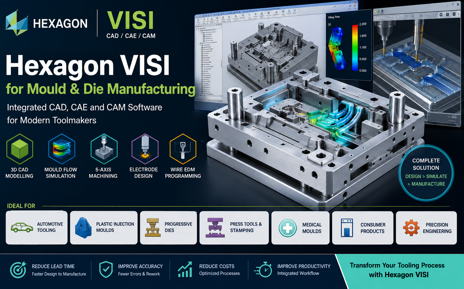
Hexagon VISI for Mould and Die Manufacturing
Discover how an integrated CAD, CAE and CAM environment can help mould makers, die manufacturers and tool rooms accelerate design, simulation and CNC manufacturing.
Instead of moving geometry repeatedly between separate CAD, simulation and CAM systems, engineering teams can use a more connected digital workflow from customer part data through mould or die design and into manufacturing.
What Is Hexagon VISI?
Hexagon VISI is specialised CAD, CAE and CAM software developed for mould makers, die manufacturers, tool rooms and precision engineering companies.
Its tooling-focused environment supports activities such as:
- 3D CAD modelling
- Geometry analysis and repair
- Core and cavity development
- Plastic injection mould design
- Injection moulding simulation
- Cooling system development
- Progressive die design
- Sheet metal forming analysis
- Electrode design
- 2.5-axis machining
- 3-axis machining
- 5-axis machining
- Wire EDM programming
- Reverse engineering
- Tool assembly management
VISI helps connect tool design, engineering validation and manufacturing within a mould-and-die-focused digital workflow.
Why Mould and Die Manufacturers Need Specialized CAD/CAM Software
Mould and die engineering involves far more than creating a 3D model. Toolmakers must consider manufacturing feasibility, parting geometry, cooling, ejection, tool movement, machining accessibility and many other factors.
A typical injection mould workflow may include:
Analyse
Check customer geometry, draft angles, parting areas and tooling feasibility.
Design
Develop core, cavity, inserts, cooling, sliders, lifters and ejection.
Validate
Use simulation and engineering analysis to identify potential problems.
Manufacture
Create CNC and EDM programs for cores, cavities, inserts and electrodes.
VISI Modelling – CAD Designed for Toolmaking
Toolmakers frequently receive complex customer CAD data containing freeform surfaces, small features or geometry that requires modification before mould design can begin.
VISI Modelling provides wireframe, surface and solid modelling capabilities for creating, editing and repairing tooling geometry.
CAD Data Preparation
Prepare and modify customer part models before starting mould or die development.
Geometry Repair
Identify and correct problematic imported geometry before downstream engineering work.
Tooling Modifications
Create tooling-specific surfaces, solids and modifications directly inside the engineering environment.
Geometry Analysis Before Tool Design
Problems identified after a mould or die has been manufactured can be expensive.
Geometry analysis therefore becomes an important early stage of tooling development.
VISI provides tools to help designers inspect and prepare component geometry before committing engineering time to downstream tooling operations.
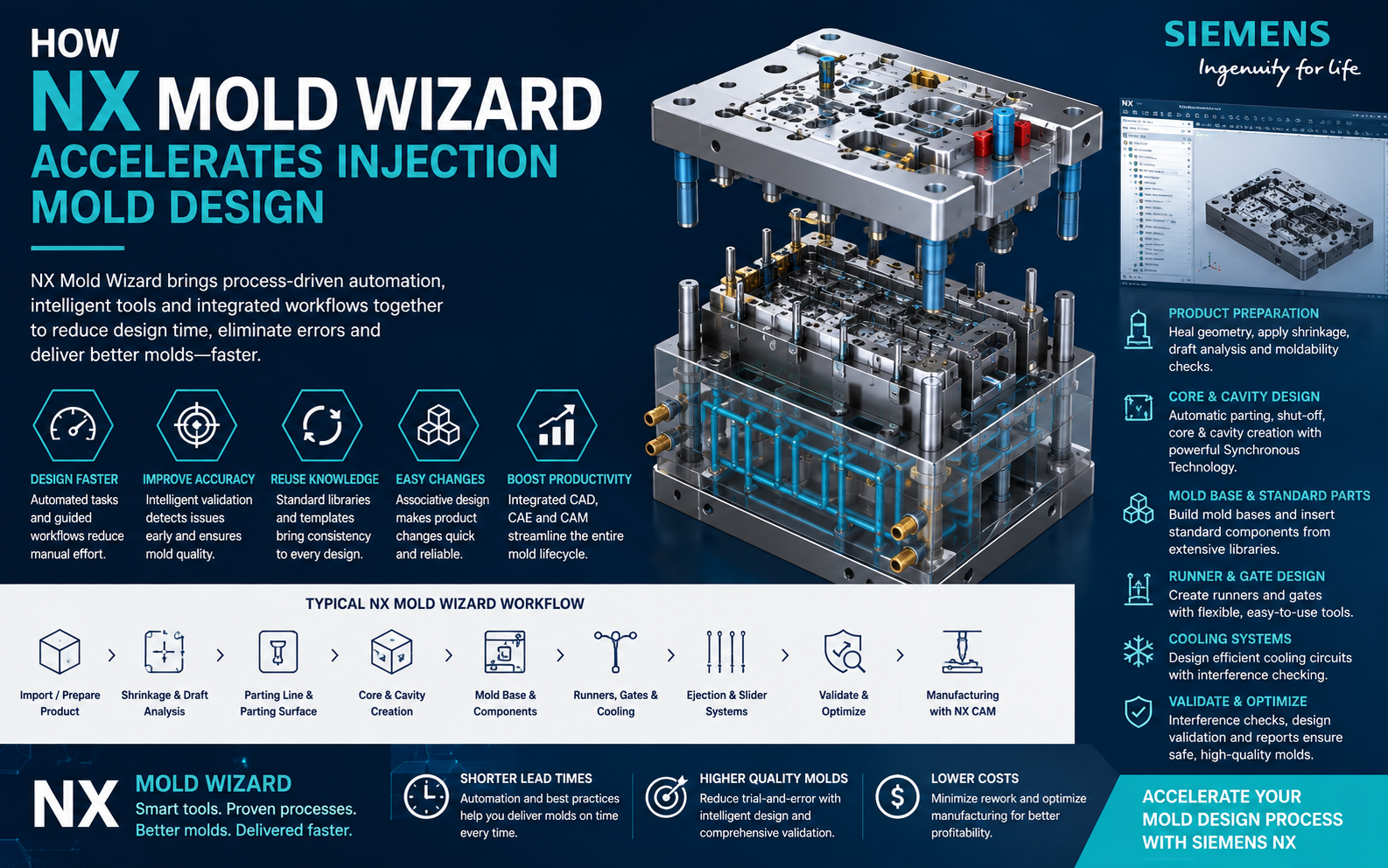
VISI Mould – Plastic Injection Mould Design
VISI provides dedicated capabilities for plastic injection mould design.
Engineers can create core and cavity geometry and develop complete tool assemblies using tooling-specific design functions.
Core & Cavity
Create tooling geometry for cores, cavities and inserts from the customer part model.
Sliders & Lifters
Develop mechanisms required for undercuts and complex moulded features.
Ejection
Develop ejector systems and related mould components.
Cooling
Create cooling channel layouts to support stable mould temperature control.
Mould Components
Use tooling component libraries to reduce repetitive design work.
Assembly Validation
Analyse the complete mould assembly and tool movement before manufacturing.
VISI Flow – Injection Moulding Simulation
A mould may be geometrically correct while still producing filling, cooling or warpage problems during actual injection moulding.
VISI Flow enables engineers to evaluate injection moulding behaviour during the digital development stage.
Engineering teams can investigate questions such as:
- Will the cavity fill correctly?
- Is the selected gate position suitable?
- Are potential filling problems present?
- How is the component cooling?
- What warpage behaviour may occur?
- Could process modifications improve the result?
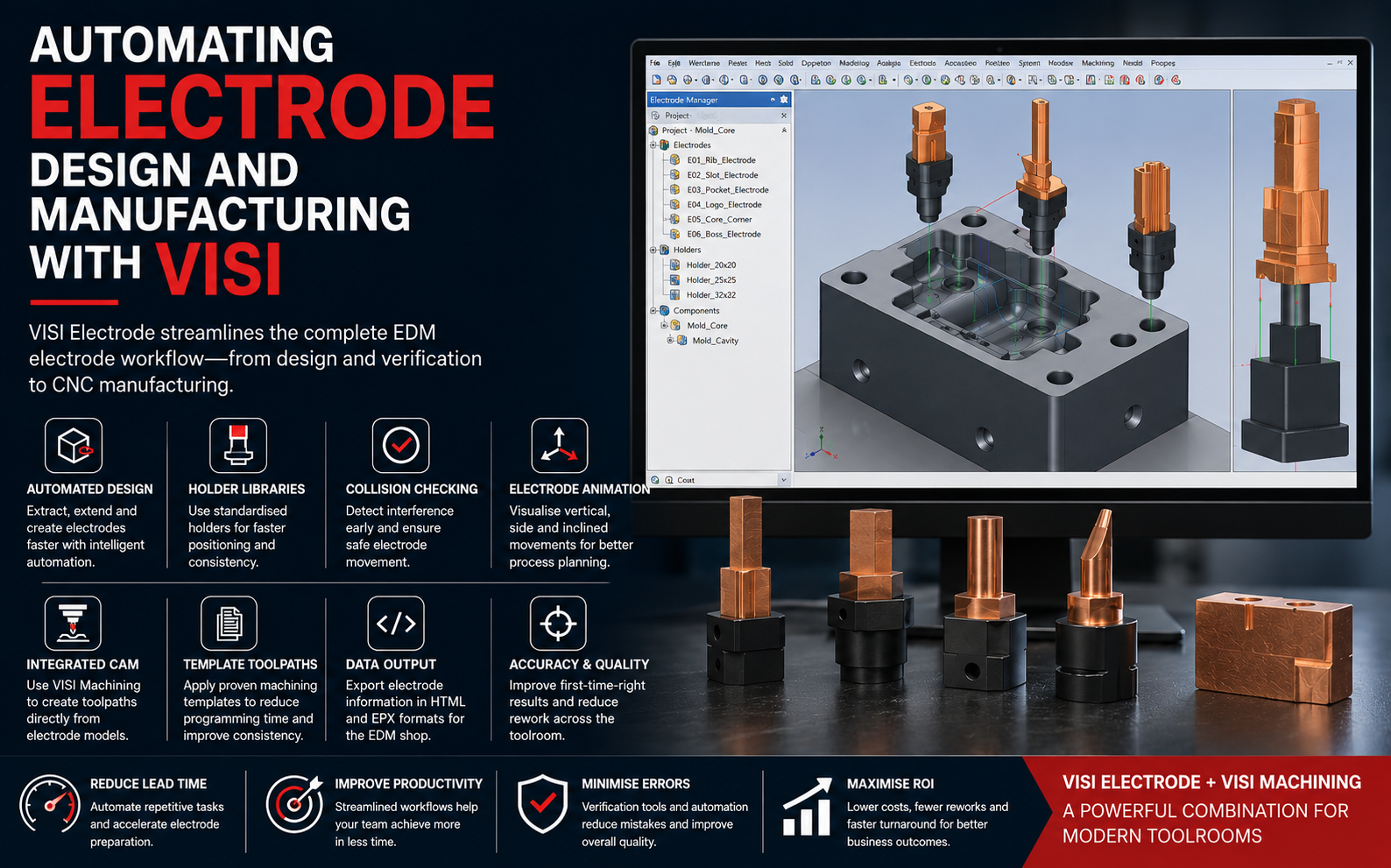
Electrode Design for EDM Manufacturing
EDM remains essential for many complex mould cavities and tooling features.
VISI provides specialised capabilities for developing electrodes from tool geometry and preparing them for manufacturing.
This can help reduce repetitive CAD preparation and create a more connected workflow between mould design, electrode preparation and EDM manufacturing.
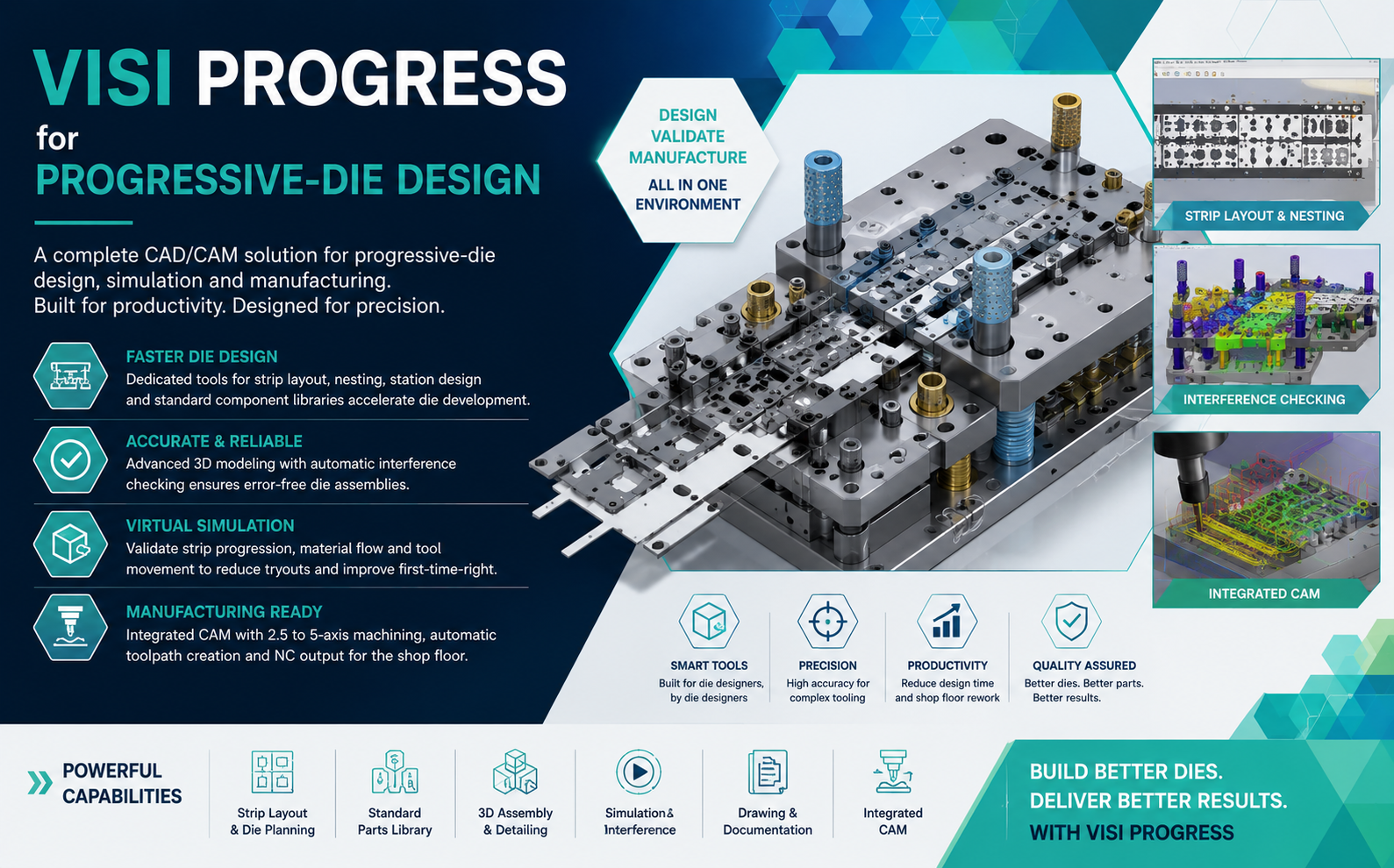
Progressive Die and Press Tool Design
VISI is also suitable for companies involved in progressive die and press tool manufacturing.
Its tooling environment can support:
- Blank development
- Part unfolding
- Strip layout creation
- Bending analysis
- Forming-related engineering
- Springback evaluation
- Die assembly development
- Tool kinematics
- Tool documentation
Integrated CAM for Mould and Die Manufacturing
After the tool has been designed and validated, VISI can continue into CNC manufacturing.
3-Axis Machining for Cores and Cavities
Mould cores, cavities and inserts frequently contain complex freeform geometry.
VISI's 3-axis machining environment supports roughing and finishing strategies required for mould and die manufacturing.
The objective is to generate efficient toolpaths while maintaining the surface quality and dimensional accuracy required by precision tooling applications.
5-Axis Machining for Complex Tooling
Five-axis machining enables toolmakers to approach difficult geometry using flexible tool orientations.
Potential benefits include:
- Improved tool accessibility
- Reduced machining setups
- Shorter tool projection
- Improved machining flexibility
- Better access to complex surfaces
Wire EDM Programming
Wire EDM remains an important manufacturing process for progressive dies, punches, mould inserts and high-precision tooling components.
Integrating Wire EDM programming into the broader tooling workflow can help reduce unnecessary data transfers and manual preparation between design and manufacturing departments.
Reverse Engineering for Tool Repair and Modification
Toolmakers are frequently required to repair or modify existing moulds and dies when complete CAD data is unavailable.
Reverse engineering capabilities can support applications including:
- Existing mould modification
- Damaged tool repair
- Legacy tooling reconstruction
- Replacement tooling components
- Engineering change projects
- Recreation of unavailable CAD geometry
A Connected Digital Workflow for Mould Manufacturing
| Stage | Engineering Activity |
|---|---|
| 1. Customer Data | Import and review product CAD geometry |
| 2. Geometry Preparation | Analyse, repair and modify customer data |
| 3. Tool Development | Create core, cavity and complete mould or die structure |
| 4. Simulation | Evaluate mould filling, cooling or forming behaviour |
| 5. Validation | Review mechanisms, clearances and manufacturing feasibility |
| 6. Electrode Development | Create electrodes for EDM operations |
| 7. CAM | Generate CNC machining strategies |
| 8. Tool Manufacturing | Machine, assemble and validate the physical tool |
Benefits of Hexagon VISI for Toolmakers
Reduce Engineering Lead Time
Tooling-specific design functions can reduce repetitive engineering operations.
Reduce Design Errors
Digital analysis and validation help detect potential problems earlier in the tooling process.
Reduce Physical Trials
Simulation allows engineering teams to investigate tooling performance before costly physical correction loops.
Improve CAD-to-CAM Continuity
A connected environment reduces unnecessary movement between independent software systems.
Improve Tool Room Productivity
Automation can help skilled engineers focus on higher-value tooling decisions.
Manage Engineering Changes
A connected tooling environment helps teams respond more effectively when customer geometry changes.
Who Should Consider Hexagon VISI?
VISI vs General-Purpose CAD Software
| Capability | General-Purpose CAD | Hexagon VISI |
|---|---|---|
| 3D Modelling | Yes | Yes |
| Surface Modelling | Yes | Yes |
| Mould Design Automation | Varies | Tooling Focused |
| Core & Cavity Development | Varies | Yes |
| Injection Moulding Simulation | Often Separate | VISI Flow |
| Progressive Die Design | Often Separate | Yes |
| Electrode Design | Often Separate | Yes |
| 3-Axis CAM | Often Separate | Yes |
| 5-Axis CAM | Often Separate | Yes |
| Wire EDM | Often Separate | Available |
| Tooling-Focused Workflow | Limited / Varies | Strong |
Hexagon VISI and the Future of Digital Toolmaking
Mould and die manufacturing is progressively moving away from isolated CAD, simulation and CNC programming activities toward more connected digital engineering workflows.
The objective is straightforward:
An integrated CAD, CAE and CAM workflow can help toolmakers improve engineering productivity while responding to increasing pressure for shorter lead times and higher tooling quality.
Hexagon VISI Support from Rheologist Gaze & Solutions
Rheologist Gaze & Solutions can support mould, die and tooling companies in evaluating VISI based on their engineering and manufacturing requirements.
Our team can help evaluate requirements related to:
- Mould design
- Die design
- CAD modelling
- Injection moulding simulation
- Electrode design
- CNC machining
- Wire EDM
- Reverse engineering
- Integrated CAD/CAM workflow
- Software implementation
- Training
- Technical support
Frequently Asked Questions About Hexagon VISI
What is Hexagon VISI used for?
Hexagon VISI is specialised CAD, CAE and CAM software for mould and die engineering. It supports modelling, mould design, simulation, progressive dies, electrodes and CNC manufacturing.
Is VISI suitable for injection mould design?
Yes. VISI provides dedicated capabilities for core and cavity development, tooling components, mould assemblies, cooling and other mould-design activities.
Does VISI include injection moulding simulation?
VISI Flow provides simulation capabilities for analysing injection moulding filling, thermal behaviour and warpage.
Can VISI be used for CNC machining?
Yes. VISI supports CAM applications including 2.5-axis, 3-axis and 5-axis machining.
Can VISI be used for progressive die design?
Yes. VISI includes capabilities for progressive die and press tool engineering.
Does VISI support electrode design?
Yes. VISI includes specialised electrode-design functionality for EDM-related tooling workflows.
Is VISI suitable for tool rooms?
Yes. Its combination of CAD, mould and die engineering, simulation, electrode development and CAM makes it particularly suitable for tool-room environments.
Conclusion
For mould and die manufacturers, software productivity depends on more than modelling speed.
The complete process must connect design, engineering validation and manufacturing.
Hexagon VISI provides a tooling-focused environment for mould makers, die manufacturers and precision engineering companies looking to create a more integrated digital workflow.
By bringing CAD, CAE and CAM capabilities closer together, toolmakers can work toward reducing engineering lead time, improving manufacturing efficiency and delivering better tooling with fewer downstream corrections.
Looking for Hexagon VISI for Your Mould & Die Operations?
Talk to Rheologist Gaze & Solutions to evaluate Hexagon VISI for mould design, die design, simulation, electrode development and CNC manufacturing.
Request a Live Demonstration info@rgees.in +91 89394 50666SEO Focus: Hexagon VISI, mould design software, mold design software, CAD CAM software for mould making, die design software, tool and die software, VISI CAD CAM, VISI Flow, plastic injection mould design software and mould manufacturing software.