
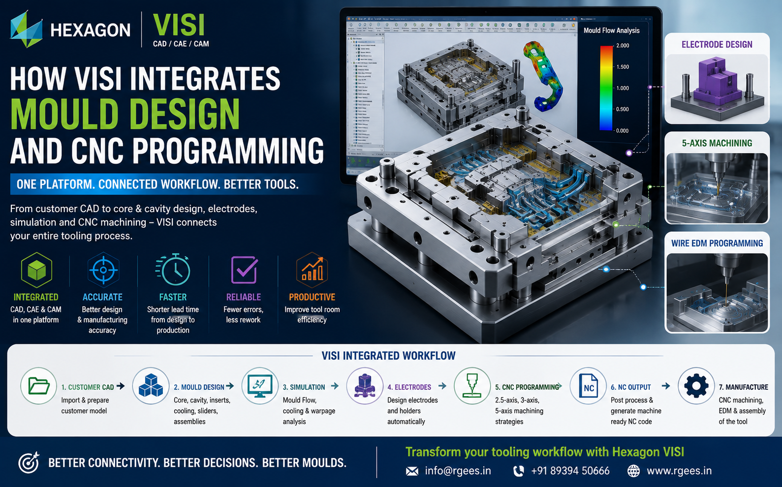
How VISI Integrates Mould Design and CNC Programming
From customer CAD geometry and core-cavity development to electrodes, CNC toolpaths and mould machining, discover how Hexagon VISI connects tool design and manufacturing within an integrated CAD/CAM workflow.
VISI combines specialised mould-design capabilities with manufacturing and CAM technologies designed for toolmakers. This means the digital model created during mould development can continue downstream toward electrode preparation and CNC programming, helping create a more connected design-to-manufacturing workflow.
The Traditional Gap Between Mould Design and CNC Programming
A mould project normally moves through several engineering departments.
When different CAD and CAM systems are used, every handover can potentially create additional work.
- CAD files may need to be exported and imported.
- Geometry may require additional repair.
- Machining boundaries may need to be recreated.
- Design changes must be communicated manually.
- Older CNC programs may need to be checked against revised models.
- Tooling knowledge can become fragmented between departments.
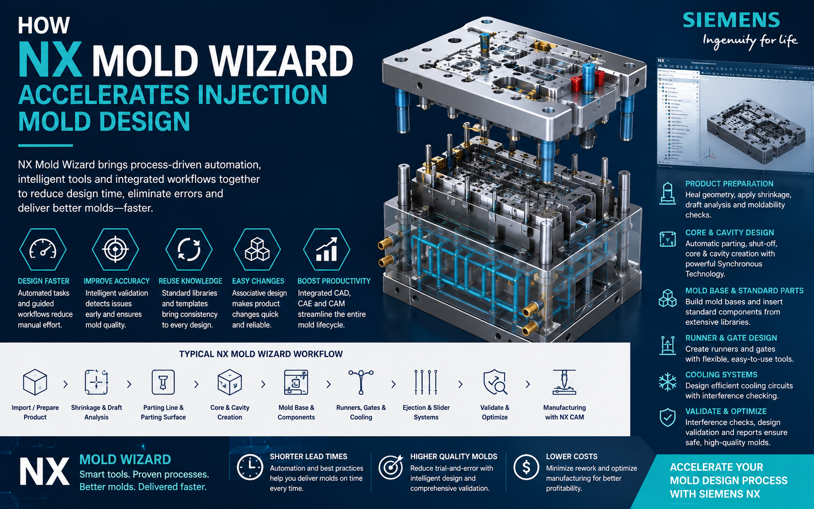
How the VISI Mould-to-CNC Workflow Works
Import & Analyse
Prepare customer CAD geometry and check the model before mould development begins.
Design the Mould
Develop core, cavity, inserts, mould base, cooling, sliders, lifters and ejection systems.
Prepare Manufacturing
Identify mould components requiring milling, drilling, EDM or Wire EDM.
Generate CNC Toolpaths
Develop machining strategies for plates, inserts, cores, cavities and other tool components.
Step 1: Preparing Customer CAD Data
Most mould projects begin with a CAD model supplied by the customer.
This data can originate from various CAD environments and may contain complex solids, surfaces or geometry requiring preparation.
VISI provides solid, surface and wireframe modelling technologies that allow toolmakers to work with imported product geometry.
CAD Import
Bring customer product geometry into the mould-development environment.
Model Analysis
Evaluate geometry for moulding feasibility and identify potential design issues.
Geometry Repair
Modify or repair geometry before downstream mould design and manufacturing operations.
Step 2: Core and Cavity Development
One of the most important stages in injection mould design is separating the product into appropriate core and cavity geometry.
VISI Mould includes dedicated functionality for analysing draft, creating split lines and separating the component into relevant tooling zones.
The mould designer can then develop:
- Core
- Cavity
- Side cores
- Shut-off surfaces
- Parting surfaces
- Inserts
- Slides
- Lifters
- Ejection mechanisms
Step 3: Building the Complete Mould Assembly
Once the core and cavity are established, designers can create the complete tooling structure.
VISI Mould provides parametric tooling structures and supplier component libraries that support the development of mould assemblies.
Mould Base
Develop the plate stack and overall tooling structure.
Standard Components
Insert standard tooling components from available supplier libraries.
Ejection System
Add ejector pins and related components according to mould requirements.
Slides & Lifters
Develop undercut-release mechanisms for complex moulded parts.
Cooling
Create 3D cooling circuits and check potential interference with other tool components.
Tool Detailing
Prepare tooling details and manufacturing documentation.
Step 4: Moving from Mould Design to Manufacturing
This stage is where CAD/CAM integration becomes particularly important.
The components developed in the mould model become the geometry required for manufacturing.
| Mould Component | Possible Manufacturing Process |
|---|---|
| Mould Plates | 2.5-axis milling, drilling and boring |
| Core | 3-axis or multi-axis CNC machining |
| Cavity | 3-axis / 5-axis machining and EDM where required |
| Inserts | CNC milling, drilling and EDM |
| Electrodes | CNC machining followed by EDM |
| Precision Profiles | Wire EDM where appropriate |
VISI 2.5-Axis CNC Programming
Mould manufacturing includes many prismatic machining operations that do not require complex 3D toolpaths.
Examples include:
- Drilling
- Counterboring
- Pocket machining
- Profile milling
- Plate machining
- Hole patterns
- Open and closed pockets
These operations are particularly important when machining mould plates and structural tooling components.
VISI 3-Axis Machining for Mould Cores and Cavities
Mould cores and cavities typically contain complex freeform geometry, requiring specialised 3-axis machining strategies.
The manufacturing process may involve:
Typical Core & Cavity CNC Workflow
5-Axis CNC Programming for Complex Mould Components
Five-axis machining can provide additional flexibility when mould components contain difficult-to-access surfaces or deep geometry.
Potential advantages include:
- Improved access to complex tooling geometry
- Reduced component setups
- Shorter cutting-tool projection
- Improved machining flexibility
- Ability to machine difficult surface regions
- Better control of tool orientation
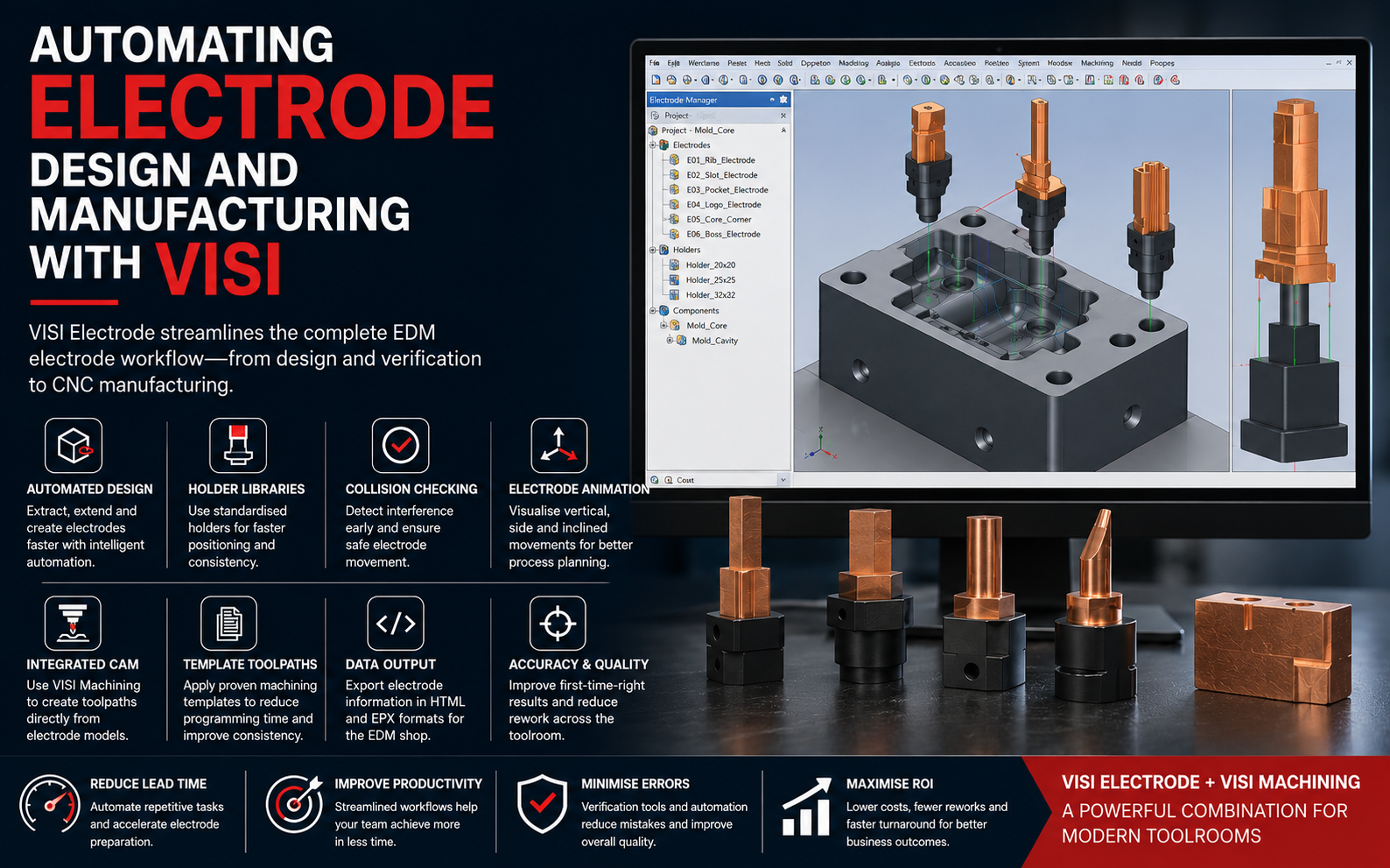
Electrode Design Connects CAD and EDM Manufacturing
Not every mould feature can be manufactured efficiently using milling.
Deep ribs, sharp internal features and difficult cavity geometry may require EDM.
VISI includes dedicated functionality for creating and managing electrodes and electrode holders.
This creates another important link between the original tooling model and downstream manufacturing operations.
Wire EDM Integration for Precision Tooling
Wire EDM is frequently used for:
- Mould inserts
- Precision slots
- Die inserts
- Punches
- Progressive dies
- High-accuracy tooling profiles
VISI's wider tooling environment includes Wire EDM programming capabilities for applications where this manufacturing process is required.
What Happens When the Customer Changes the Part Design?
Engineering changes are common during mould development.
A customer may modify:
- Wall thickness
- Rib geometry
- Boss dimensions
- Product shape
- Hole positions
- Assembly interfaces
In disconnected CAD/CAM workflows, these changes can require several manual steps before manufacturing can continue.
VISI Mould includes functionality for recognising design changes and maintaining greater continuity throughout the tooling workflow.
The Complete VISI Design-to-CNC Workflow
| Stage | Activity | Output |
|---|---|---|
| 1 | Customer CAD Import | Product model |
| 2 | Geometry Analysis | Manufacturing-ready geometry |
| 3 | Core / Cavity Development | Tooling geometry |
| 4 | Mould Assembly | Complete mould design |
| 5 | Cooling / Tool Validation | Validated mould structure |
| 6 | Electrode Preparation | EDM electrode models |
| 7 | CAM Programming | CNC toolpaths |
| 8 | NC Program | Machine-ready NC code |
| 9 | CNC / EDM Manufacturing | Physical mould components |
Benefits of Integrating Mould Design and CNC Programming
Better Design-to-Manufacturing Continuity
Reduce unnecessary geometry transfers between mould design and manufacturing teams.
Shorter Programming Time
Manufacturing teams can begin with geometry already developed and prepared during the tooling process.
Reduce Errors
Fewer software handovers can help reduce errors associated with recreating manufacturing geometry.
Handle Design Changes Better
Connected workflows make it easier for tooling and manufacturing teams to react to engineering revisions.
Improve CNC Productivity
Use dedicated manufacturing strategies for plates, cores, cavities and tooling components.
Improve Tool-Room Productivity
A connected digital process can help shorten the overall path from customer model to finished mould.
Traditional CAD/CAM Workflow vs Integrated VISI Workflow
| Process | Disconnected CAD + CAM | Integrated VISI Workflow |
|---|---|---|
| Product Geometry | Imported into CAD | Prepared within tooling environment |
| Core & Cavity | Created in mould-design software | Created using specialised VISI mould tools |
| Transfer to CAM | Often requires export/import | More connected manufacturing workflow |
| Geometry Preparation | May be repeated | Reduced duplication |
| Electrodes | May require separate workflow | Dedicated electrode functionality |
| CNC Machining | Separate CAM environment | Integrated tooling/CAM ecosystem |
| Engineering Changes | More manual coordination | Greater CAD/CAM continuity |
Who Can Benefit from an Integrated VISI Workflow?
From CAD Model to CNC Machine: Why Integration Matters
For a mould manufacturer, the goal is not simply to complete the CAD design faster.
The real objective is to reduce the complete design-to-manufacturing lead time.
Every unnecessary file conversion, repeated geometry preparation and manual communication step adds time to the tooling project.
This is particularly important for tool rooms competing on delivery time, machining cost, tool quality and engineering responsiveness.
Implement Hexagon VISI with Rheologist Gaze & Solutions
Rheologist Gaze & Solutions can support mould and die manufacturers that want to evaluate an integrated VISI workflow for tool design and CNC manufacturing.
Our discussions can cover:
- Existing mould-design workflow
- Customer CAD data handling
- Core and cavity development
- Mould assembly design
- Cooling and tooling validation
- Electrode development
- 2.5-axis CNC programming
- 3-axis mould machining
- 5-axis machining
- Wire EDM programming
- CAD-to-CAM workflow optimization
- Software implementation
- Training and technical support
Frequently Asked Questions
How does VISI integrate mould design and CNC programming?
VISI provides specialised mould-design and CAM capabilities within a connected tooling environment, enabling geometry developed during the mould-design stage to continue into downstream manufacturing workflows.
Can VISI machine mould cores and cavities?
VISI includes CAM capabilities that can be applied to complex mould components such as cores, cavities, inserts and tooling plates.
Does VISI support 5-axis CNC machining?
VISI's manufacturing portfolio includes multi-axis machining capabilities, including 5-axis applications.
Can VISI create electrodes for EDM?
Yes. VISI includes dedicated electrode-design functionality for creating and managing electrodes and their holders.
Can VISI handle customer design changes?
VISI Mould includes design-change recognition capabilities designed to help tooling teams manage changes during mould development.
Is VISI suitable for complete mould manufacturing?
VISI is developed specifically for the mould and die sector and combines tooling-focused CAD, CAE and CAM technologies for processes from model preparation and tool design through downstream manufacturing.
Conclusion: Connect Mould Design Directly to Manufacturing
Modern mould manufacturing requires more than powerful CAD software and powerful CAM software.
It requires a connected engineering workflow between the two.
Hexagon VISI provides mould and die manufacturers with an integrated environment for moving from customer geometry through mould design and toward CNC and EDM manufacturing.
By reducing unnecessary handovers between design and manufacturing, toolmakers can work toward:
- Shorter lead times
- Faster CNC programming
- Fewer geometry-related errors
- Better response to engineering changes
- Improved tool-room productivity
- Better design-to-manufacturing continuity
Want to Connect Your Mould Design and CNC Programming?
Talk to Rheologist Gaze & Solutions about Hexagon VISI for integrated mould design, electrode development and CNC programming.
Request a Live Demonstration info@rgees.in +91 89394 50666SEO Topics: Hexagon VISI CAD CAM, VISI mould design, VISI CNC programming, mould design software, CNC programming for mould making, injection mould design software, mould manufacturing software, 3-axis mould machining, 5-axis CNC machining, electrode design, tool room CAD CAM, core cavity design, integrated CAD CAM for toolmakers.