
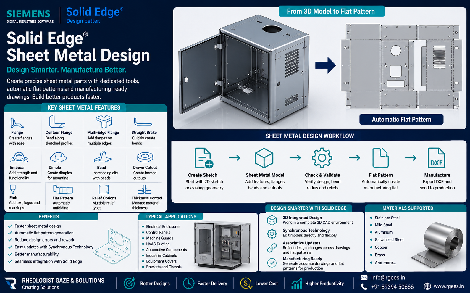
Solid Edge Sheet Metal Design: Features and Applications
Design sheet metal components with dedicated bends, flanges, forming features and manufacturing-ready flat patterns using Siemens Solid Edge.
Siemens positions Solid Edge as providing dedicated sheet metal design capabilities rather than relying only on general-purpose modelling. It includes specialised features and automatic flat-pattern development for downstream production.
What Is Sheet Metal Design?
Sheet metal design is the engineering process of creating components that will ultimately be manufactured from flat sheet material through operations such as:
- Laser cutting
- Plasma cutting
- Turret punching
- Waterjet cutting
- Bending
- Press brake forming
- Stamping
- Drawing
- Rolling
- Welding
The CAD model therefore needs to represent both:
Typical Solid Edge Sheet Metal Workflow
Create Geometry
Start from a sketch, existing solid model or imported component geometry.
Add Sheet Metal Features
Create walls, bends, flanges, cutouts and forming features.
Check Manufacturability
Review bend conditions, clearances, reliefs and the overall component design.
Create Flat Pattern
Automatically unfold the component for drawings and fabrication.
Key Solid Edge Sheet Metal Features
1. Flange Design
Flanges are among the most common features in sheet metal components. They are used to:
- Join components
- Create enclosure walls
- Add stiffness
- Provide mounting surfaces
- Develop structural edges
Solid Edge provides dedicated sheet metal flange capabilities, including multi-edge and contour flange workflows. :contentReference[oaicite:1]{index=1}
2. Bend Design and Bend Parameters
A sheet metal component cannot simply be modelled as an infinitely thin surface.
The CAD system must understand:
- Material thickness
- Inside bend radius
- Bend angle
- Bend direction
- Neutral-axis behaviour
- Bend allowance
- Bend relief
These parameters influence the developed flat pattern and therefore directly affect manufacturing accuracy.
3. Synchronous Technology for Sheet Metal Editing
One of Solid Edge's distinguishing modelling technologies is Synchronous Technology.
It allows engineers to work more directly with geometry and make certain design edits without relying entirely on a long feature-history sequence.
Siemens highlights this type of direct editing for sheet metal workflows, including editing features without unnecessarily regenerating unrelated downstream geometry. :contentReference[oaicite:2]{index=2}
4. Sheet Metal Forming Features
Real fabricated components frequently contain features created using press operations rather than simple cuts and bends.
Embosses
Raised or recessed geometry used for stiffness, spacing and functional features.
Dimples
Local formed features commonly used around mounting points and holes.
Beads
Formed ribs or beads can increase rigidity without significantly increasing material thickness.
These are examples of the specialised features Siemens lists for Solid Edge Sheet Metal. :contentReference[oaicite:3]{index=3}
5. Automatic Flat Pattern Generation
One of the most important outputs from a sheet metal CAD model is the flat pattern.
The flat pattern represents the component before bending and forming. It can be used for:
- Laser cutting
- Plasma cutting
- Waterjet cutting
- Punching
- Nesting
- Cost calculation
- Production drawings
Siemens states that Solid Edge can automatically create flat patterns, including more complex flattening requirements for press work. :contentReference[oaicite:4]{index=4}
6. Preparing Geometry for Fabrication
After the flat pattern is created, manufacturing geometry can be prepared for downstream cutting and forming processes.
This design-to-fabrication workflow is important for manufacturers that use CNC:
- Laser cutting machines
- Plasma cutters
- Waterjet systems
- Turret punch presses
- Press brakes
Siemens customer examples document Solid Edge sheet metal workflows where final contour geometry is passed downstream in DXF format for cutting operations. :contentReference[oaicite:5]{index=5}
7. Tab-and-Slot Design for Fabricated Assemblies
Tab-and-slot construction can simplify positioning and assembly of sheet metal parts before welding.
The current Designcenter Solid Edge 2026 release includes automated tab-and-slot functionality for faster creation of interlocking joints. :contentReference[oaicite:6]{index=6}
This type of feature can help:
- Reduce assembly positioning time
- Improve repeatability
- Reduce fixture dependency
- Support welded fabrication
Design for Sheet Metal Manufacturability
Good sheet metal CAD is not only about creating the required shape. The part must also be practical to manufacture.
Bend Clearance
Provide adequate clearance so adjacent features do not interfere during bending.
Corner Relief
Use appropriate relief geometry to reduce tearing and deformation around corners.
Hole-to-Bend Distance
Position holes carefully so bending does not unnecessarily distort them.
Consistent Thickness
Maintain appropriate sheet thickness throughout the component.
Tool Accessibility
Consider whether the required press brake or forming tool can access the bend.
Production Sequence
Review whether the selected bends can be manufactured in a practical order.
Design Sheet Metal Parts from 2D Sketches
Many fabricated products begin with a simple 2D profile.
Solid Edge can create sheet metal models from sketches and then add manufacturing-oriented features such as bends, flanges, dimples and beads. Siemens customer documentation specifically highlights this workflow. :contentReference[oaicite:7]{index=7}
Converting Existing Geometry into Sheet Metal
Not every sheet metal project starts directly in the sheet metal environment.
Engineers may receive:
- Imported customer CAD models
- Concept solids
- Legacy geometry
- Supplier CAD data
A practical CAD workflow should allow engineers to adapt such geometry for manufacturing rather than redesigning every part from the beginning.
Applications of Solid Edge Sheet Metal Design
Sheet Metal Design for Electrical Enclosures
Electrical and electronic products frequently use fabricated metal enclosures.
Engineers may need to design:
- Outer cabinets
- Internal mounting panels
- Doors
- Brackets
- Ventilation openings
- Cable-entry cutouts
- Mounting flanges
Sheet metal-specific modelling allows these components to be developed as manufacturable parts instead of generic thin solid models.
Sheet Metal Design for Machinery
Machine manufacturers use sheet metal extensively for:
- Machine covers
- Safety guards
- Access doors
- Control cabinets
- Internal brackets
- Hoppers
- Chutes
Solid Edge's broader assembly capabilities also allow sheet metal, weldments, tubes, pipes and other components to be represented in the same digital machine assembly. :contentReference[oaicite:8]{index=8}
Sheet Metal Applications in Automotive and Transportation
Automotive and transportation suppliers can use sheet metal CAD for components including:
- Brackets
- Battery covers
- Electronic housings
- Protective panels
- Structural fabricated components
- Mounting assemblies
Benefits of Solid Edge Sheet Metal Design
Faster Sheet Metal Design
Use dedicated sheet metal functions rather than constructing every feature manually with generic CAD operations.
Accurate Flat Patterns
Generate manufacturing geometry directly from the 3D folded component.
Flexible Engineering Changes
Direct-editing capabilities can help engineers respond faster to late design revisions.
Better Manufacturability
Design using sheet metal-specific features that reflect actual fabrication processes.
Reduce Drawing Errors
Keep flat patterns and drawings closely connected to the 3D design.
Improve Fabrication Productivity
Move more efficiently from design through cutting, bending and assembly.
General 3D CAD vs Dedicated Sheet Metal CAD
| Capability | General Solid Modelling | Solid Edge Sheet Metal |
|---|---|---|
| 3D Geometry | Yes | Yes |
| Material Thickness Awareness | Manual / varies | Sheet metal specific |
| Bend Features | May require generic modelling | Dedicated |
| Flanges | Generic modelling | Dedicated |
| Dimples / Beads | Manual modelling | Dedicated features |
| Flat Pattern | Limited / manual | Automatic |
| Fabrication Workflow | General purpose | Manufacturing focused |
| Sheet Metal Engineering Changes | Depends on CAD workflow | Supported with dedicated and synchronous editing |
From 3D CAD to Fabrication
The value of sheet metal CAD is not simply the ability to create a good-looking 3D model.
The real objective is to create engineering data that can move efficiently into manufacturing.
Siemens describes Solid Edge as streamlining the sheet metal product development process from CAD design through flat pattern and drawing development. :contentReference[oaicite:9]{index=9}
Sheet Metal Enhancements in Designcenter Solid Edge 2026
The current Designcenter Solid Edge 2026 release continues to add sheet metal manufacturing improvements.
Siemens highlights enhancements including:
- Tab-and-slot automation
- Expanded etching support
- Improved flange trimming
- Additional thin-wall modelling controls
These enhancements are intended to improve design speed, manufacturability and manufacturing preparation. :contentReference[oaicite:10]{index=10}
Who Should Consider Solid Edge Sheet Metal?
Sheet Metal Fabricators
Create manufacturing-ready 3D parts and flat patterns.
Machine Manufacturers
Design guards, covers, cabinets and fabricated machine structures.
Electrical Panel Builders
Develop enclosure systems, doors, panels and mounting brackets.
HVAC Manufacturers
Create ducts, housings and other formed metal components.
Automotive Suppliers
Develop brackets, covers, housings and precision formed components.
Engineering SMEs
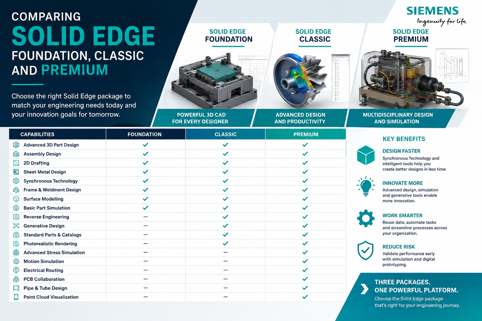
Combine part, assembly and sheet metal design in a broader 3D CAD environment.
Solid Edge Sheet Metal Support from Rheologist Gaze & Solutions
Rheologist Gaze & Solutions can support manufacturers evaluating Siemens Solid Edge for sheet metal product development.
Our discussions can cover:
- Sheet metal CAD requirements
- Flange and bend design
- Flat-pattern generation
- Fabrication drawings
- DXF manufacturing workflows
- Machine enclosure design
- Electrical cabinet design
- Assembly design
- Migration from 2D CAD
- Solid Edge implementation
- Training
- Technical support
Frequently Asked Questions About Solid Edge Sheet Metal
What is Solid Edge Sheet Metal?
Solid Edge Sheet Metal is a dedicated CAD environment for designing manufacturable sheet metal parts using sheet metal-specific bends, flanges, formed features and flat patterns.
Can Solid Edge automatically create a flat pattern?
Yes. Solid Edge automatically creates flat patterns from the 3D sheet metal design, including complex flattening requirements for production.
What sheet metal features are available in Solid Edge?
Dedicated features include flanges, contour flanges, multi-edge flanges, embosses, dimples, beads, drawn cutouts, etching and other sheet metal manufacturing features.
Can Solid Edge be used for electrical enclosure design?
Yes. Solid Edge is suitable for designing cabinets, panels, doors, brackets and many other fabricated enclosure components.
Can I export sheet metal flat patterns for laser cutting?
Flat pattern geometry can be prepared for downstream fabrication workflows such as laser, plasma, waterjet and punching processes, depending on the required manufacturing format.
Can Solid Edge handle sheet metal design changes?
Yes. Solid Edge combines dedicated sheet metal capabilities with Synchronous Technology, supporting flexible edits to sheet metal geometry.
Conclusion: Design Sheet Metal with Manufacturing in Mind
Sheet metal CAD should do more than represent the final component.
It should understand how that part will actually be cut, bent, formed and assembled.
Solid Edge Sheet Metal provides specialised tools for creating manufacturable sheet metal components while automatically connecting the folded 3D model with the required flat pattern.
This connected workflow can help manufacturers shorten design lead time, reduce repetitive engineering and move from CAD to fabrication with greater confidence.
Looking for Professional Sheet Metal CAD Software?
Talk to Rheologist Gaze & Solutions about Siemens Solid Edge for sheet metal design, machinery, enclosures and fabrication workflows.
Request a Solid Edge Demonstration info@rgees.in +91 89394 50666SEO Focus Keywords: Solid Edge Sheet Metal, Solid Edge sheet metal design, sheet metal CAD software, sheet metal design software, sheet metal fabrication software, flat pattern CAD, sheet metal unfolding, sheet metal enclosure design, sheet metal bend software, flange design software, Siemens Solid Edge, sheet metal CAD India.